
MECHANICS OF MATERIALS (LOOSE)-W/ACCESS
10th Edition
ISBN: 9780134583228
Author: HIBBELER
Publisher: PEARSON
expand_more
expand_more
format_list_bulleted
Videos
Textbook Question
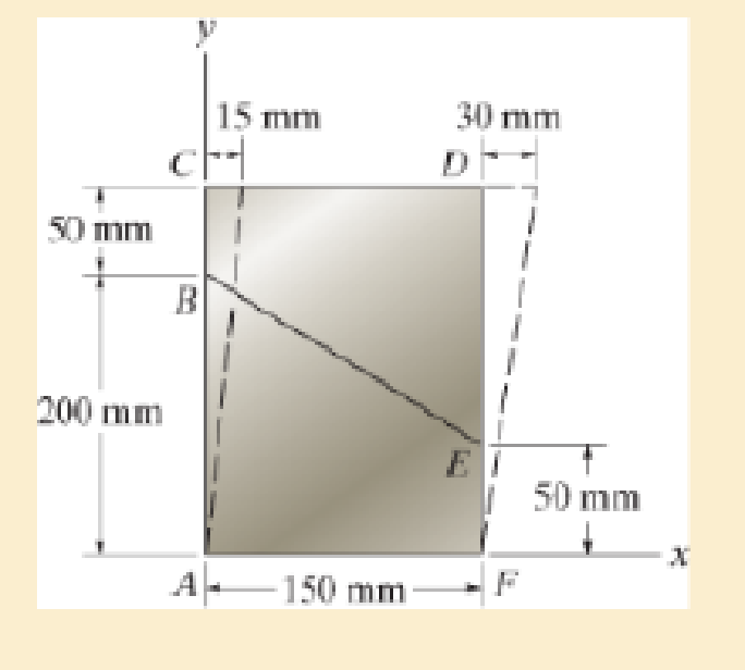
Chapter 2.2, Problem 2.13P
The material distorts into the dashed position shown. Determine the average normal strains along the diagonals AD and CF.
Expert Solution & Answer

Trending nowThis is a popular solution!

Students have asked these similar questions
Procedure:
1- Cartesian system, 2D3D,
type of support
2- Free body diagram
3 - Find the support reactions
4- If you find a negative
number then flip the force
5- Find the internal force
3D
∑Fx=0
∑Fy=0
∑Fz=0
∑Mx=0
∑My=0
ΣMz=0
2D
ΣFx=0
ΣFy=0
ΣMz=0
5- Use method of section
and cut the element
where you want to find
the internal force and
keep either side of the
Procedure:1- Cartesian system, 2D3D,type of support2- Free body diagram3 - Find the support reactions4- If you find a negativenumber then flip the force5- Find the internal force3D∑Fx=0∑Fy=0∑Fz=0∑Mx=0∑My=0\Sigma Mz=02D\Sigma Fx=0\Sigma Fy=0\Sigma Mz=05- Use method of sectionand cut the elementwhere you want to findthe internal force andkeep either side of the
Procedure: 1- Cartesian system, 2(D)/(3)D, type of support 2- Free body diagram 3 - Find the support reactions 4- If you find a negative number then flip the force 5- Find the internal force 3D \sum Fx=0 \sum Fy=0 \sum Fz=0 \sum Mx=0 \sum My=0 \Sigma Mz=0 2D \Sigma Fx=0 \Sigma Fy=0 \Sigma Mz=0 5- Use method of section and cut the element where you want to find the internal force and keep either side of the section
Chapter 2 Solutions
MECHANICS OF MATERIALS (LOOSE)-W/ACCESS
Ch. 2.2 - A loading causes the member to deform into the...Ch. 2.2 - A loading causes the mamber to deform into the...Ch. 2.2 - A loading causes the wires to elongate into the...Ch. 2.2 - A loading causes the block to deform into the...Ch. 2.2 - A loading causes the block to deform into the...Ch. 2.2 - When force P is applied to the rigid arm ABC,...Ch. 2.2 - If the force P causes the rigid arm ABC to rotate...Ch. 2.2 - The rectangular plate is deformed into the shape...Ch. 2.2 - The triangular plate is deformed into the shape...Ch. 2.2 - The square plate is deformed into the shape shown...
Ch. 2.2 - The square deforms into the position shown by the...Ch. 2.2 - The pin-connected rigid rods AB and BC are...Ch. 2.2 - The wire AB is unstretched when = 45. If a load...Ch. 2.2 - If a horizontal load applied to the bar AC causes...Ch. 2.2 - Determine the shear strain xy at corners A and B...Ch. 2.2 - Determine the shear strain xy at corners D and C...Ch. 2.2 - The material distorts into the dashed position...Ch. 2.2 - The material distorts into the dashed position...Ch. 2.2 - Part of a control linkage for an airplane consists...Ch. 2.2 - Part of a control linkage for an airplane consists...Ch. 2.2 - The nylon cord has an original length L and is...Ch. 2.2 - A thin wire, lying along the x axis, is strained...Ch. 2.2 - Determine the shear strain xy at corners A and B...Ch. 2.2 - Determine the shear strain xy at corners D and C...Ch. 2.2 - Determine the average normal strain that occurs...Ch. 2.2 - The corners of the square plate are given the...Ch. 2.2 - The triangular plate is fixed at its base, and its...Ch. 2.2 - The triangular plate is fixed at its base, and its...Ch. 2.2 - The triangular plate is fixed at its base, and its...Ch. 2.2 - The polysulfone block is glued at its top and...Ch. 2.2 - The corners of the square plate are given the...Ch. 2.2 - The corners of the square plate are given the...Ch. 2.2 - The block is deformed into the position shown by...Ch. 2.2 - The rectangular plate is deformed into the shape...Ch. 2.2 - The rectangular plate is deformed into the shape...Ch. 2.2 - The nonuniform loading causes a normal strain in...Ch. 2.2 - The rectangular plate undergoes a deformation...Ch. 2.2 - The fiber AB has a length L and orientation . If...Ch. 2.2 - If the normal strain is defined in reference to...
Knowledge Booster


Learn more about
Need a deep-dive on the concept behind this application? Look no further. Learn more about this topic, mechanical-engineering and related others by exploring similar questions and additional content below.Similar questions
- Procedure: 1- Cartesian system, 2(D)/(3)D, type of support 2- Free body diagram 3 - Find the support reactions 4- If you find a negative number then flip the force 5- Find the internal force 3D \sum Fx=0 \sum Fy=0 \sum Fz=0 \sum Mx=0 \sum My=0 \Sigma Mz=0 2D \Sigma Fx=0 \Sigma Fy=0 \Sigma Mz=0 5- Use method of section and cut the element where you want to find the internal force and keep either side of the sectionarrow_forwardFor each system below with transfer function G(s), plot the pole(s) on the s-plane. and indicate whether the system is: (a) "stable" (i.e., a bounded input will always result in a bounded output), (b) "marginally stable," or (c) "unstable" Sketch a rough graph of the time response to a step input. 8 a) G(s) = 5-5 8 b) G(s) = c) G(s) = = s+5 3s + 8 s² - 2s +2 3s +8 d) G(s): = s²+2s+2 3s+8 e) G(s): = s² +9 f) G(s): 8 00 == Sarrow_forwardPlease answer the following question. Include all work and plase explain. Graphs are provided below. "Consider the Mg (Magnesium) - Ni (Nickel) phase diagram shown below. This phase diagram contains two eutectic reactions and two intermediate phases (Mg2Ni and MgNi2). At a temperature of 505oC, determine what the composition of an alloy would need to be to contain a mass fraction of 0.20 Mg and 0.80 Mg2Ni."arrow_forward
- The triangular plate, having a 90∘∘ angle at AA, supports the load PP = 370 lblb as shown in (Figure 1).arrow_forwardDesign a 4-bar linkage to carry the body in Figure 1 through the two positions P1 and P2 at the angles shown in the figure. Use analytical synthesis with the free choice values z = 1.075, q= 210°, ß2 = −27° for left side and s = 1.24, y= 74°, ½ = − 40° for right side. φ 1.236 P2 147.5° 210° 2.138 P1 Figure 1 Xarrow_forwardDesign a 4-bar linkage to carry the body in Figure 1 through the two positions P1 and P2 at the angles shown in the figure. Use analytical synthesis with the free choice values z = 1.075, q= 210°, B₂ = −27° for left side and s = 1.24, y= 74°, ½ = − 40° for right side. 1.236 P2 147.5° 210° P1 Figure 1 2.138 Xarrow_forward
- can you explain how in a coordinate frame transformation: v = {v_n}^T {n-hat} and then it was found that {n-hat} = [C]^T {b-hat} so v_n = {v_n}^T [C]^T {b-hat}, how does that equation go from that to this --> v_n = [C]^T v_barrow_forward6) If (k = 0,7 cm) find Imax for figure below. 225mm 100mm ثلاثاء. 100mm 150mm 75mm Ans: Tmax=45:27 N/cm F-400 Narrow_forwardThe man has a weight W and stands halfway along the beam. The beam is not smooth, but the planes at A and B are smooth (and plane A is horizontal). Determine the magnitude of the tension in the cord in terms of W and θ.arrow_forward
arrow_back_ios
SEE MORE QUESTIONS
arrow_forward_ios
Recommended textbooks for you
 Mechanics of Materials (MindTap Course List)Mechanical EngineeringISBN:9781337093347Author:Barry J. Goodno, James M. GerePublisher:Cengage Learning
Mechanics of Materials (MindTap Course List)
Mechanical Engineering
ISBN:9781337093347
Author:Barry J. Goodno, James M. Gere
Publisher:Cengage Learning
Lec21, Part 5, Strain transformation; Author: Mechanics of Materials (Libre);https://www.youtube.com/watch?v=sgJvz5j_ubM;License: Standard Youtube License