Physics (5th Edition)
5th Edition
ISBN: 9780321976444
Author: James S. Walker
Publisher: PEARSON
expand_more
expand_more
format_list_bulleted
Videos
Textbook Question
Chapter 21.4, Problem 4EYU
The two circuits shown in Figure 21-17 have identical battenes and resistors, but the arrangement of the resistors is different. Is the current in circuit 1 greater than, less than, or equal to the current in circuit 2? Explain. 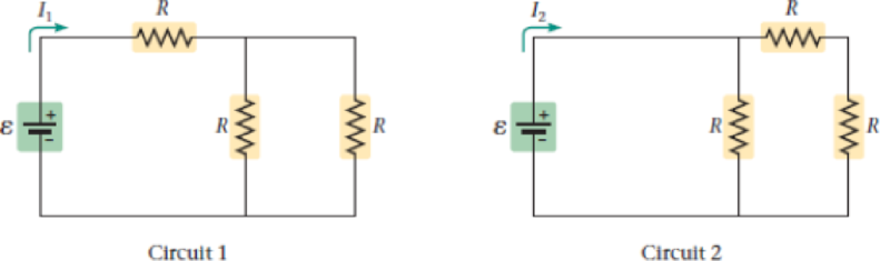
Expert Solution & Answer
Want to see the full answer?
Check out a sample textbook solution
Students have asked these similar questions
A long, straight wire carries a current of 10 A along what we’ll define to the be x-axis. A square loopin the x-y plane with side length 0.1 m is placed near the wire such that its closest side is parallel tothe wire and 0.05 m away.• Calculate the magnetic flux through the loop using Ampere’s law.
Describe the motion of a charged particle entering a uniform magnetic field at an angle to the fieldlines. Include a diagram showing the velocity vector, magnetic field lines, and the path of the particle.
Discuss the differences between the Biot-Savart law and Coulomb’s law in terms of their applicationsand the physical quantities they describe.
Chapter 21 Solutions
Physics (5th Edition)
Ch. 21.1 - Enhance Your Understanding 1. The following...Ch. 21.2 - Enhance Your Understanding 2. If the voltage and...Ch. 21.3 - Enhance Your Understanding 3. In the following...Ch. 21.4 - The two circuits shown in Figure 21-17 have...Ch. 21.5 - Prob. 5EYUCh. 21.6 - Do two capacitors give a larger equivalent...Ch. 21.7 - Give a symbolic expression for the current that...Ch. 21 - Your body is composed of electric charges. Does it...Ch. 21 - Suppose you charge a comb by rubbing it through...Ch. 21 - An electron moving through a wire has an average...
Ch. 21 - Are car headlights connected in series or...Ch. 21 - Is it possible to connect a group of resistors of...Ch. 21 - What physical quantity do resistors connected in...Ch. 21 - What physical quantity do resistors connected in...Ch. 21 - Explain how electrical devices can begin operating...Ch. 21 - Explain the difference between resistivity and...Ch. 21 - Explain why birds can roost on high-voltage wires...Ch. 21 - Consider the circuit shown in Figure 21-36, in...Ch. 21 - A flashlight bulb carries a current of 0.38 A for...Ch. 21 - Predict/Calculate A car battery does 360 J of work...Ch. 21 - Highly sensitive ammeters can measure currents as...Ch. 21 - A television set connected to a 120-V outlet...Ch. 21 - BIO Pacemaker Batteries Pacemakers designed for...Ch. 21 - A conducting wire is quadrupled in length and...Ch. 21 - Figure 21-37 shows a plot of current versus...Ch. 21 - Predict/Explain Current-versus-voltage plots for...Ch. 21 - Prob. 9PCECh. 21 - When a potential difference of 12 V is applied to...Ch. 21 - Prob. 11PCECh. 21 - Prob. 12PCECh. 21 - Transcranial Direct-Current Stimulation In a tDCS...Ch. 21 - The four conducting cylinders shown in Figure...Ch. 21 - Predict/Calculate A bird lands on a bare copper...Ch. 21 - Prob. 16PCECh. 21 - Predict/Calculate BIO Current Through a Cell...Ch. 21 - Prob. 18PCECh. 21 - Prob. 19PCECh. 21 - BIO Resistance and Current in the Human Finger The...Ch. 21 - If a potential difference V is maintained between...Ch. 21 - Light A has four times the power rating of light B...Ch. 21 - Two lightbulbs operate on the same potential...Ch. 21 - Problems and Conceptual Exercises Section 21-3...Ch. 21 - A 65-V generator supplies 4.8 kW of power. How...Ch. 21 - A portable CD player operates with a current of 18...Ch. 21 - Find the power dissipated in a 22- electric heater...Ch. 21 - The current in a 120-V reading lamp is 2.6 A. If...Ch. 21 - Circuit A in a house has a voltage of 208 V and is...Ch. 21 - Predict/Calculate A 65-W lightbulb operates on a...Ch. 21 - Rating Car Batteries Car batteries are rated by...Ch. 21 - Predict/Explain A dozen identical lightbulbs are...Ch. 21 - A circuit consists of three resistors, R1 R2 R3,...Ch. 21 - Predict/Explain Two resistors are connected in...Ch. 21 - What is the minimum number of 88- resistors that...Ch. 21 - Find the equivalent resistance between points A...Ch. 21 - A 9.00-V battery is connected across the terminals...Ch. 21 - Holiday Lights In a string of holiday lights, 50...Ch. 21 - Your toaster has a power cord with a resistance of...Ch. 21 - Prob. 40PCECh. 21 - Predict/Calculate Three resistors, 11, 53 , and R,...Ch. 21 - A circuit consists of a battery connected to three...Ch. 21 - Predict/Calculate Three resistors, 22 , 67 , and...Ch. 21 - Prob. 44PCECh. 21 - The equivalent resistance between points A and B...Ch. 21 - Find the equivalent resistance between points A...Ch. 21 - How many 23-W lightbulbs can be connected in...Ch. 21 - The circuit in Figure 21-43 includes a battery...Ch. 21 - Predict/Calculate A 12-V battery is connected to...Ch. 21 - Predict/Calculate The terminals A and B in Figure...Ch. 21 - Predict/Calculate Suppose the battery in Figure...Ch. 21 - Predict/Calculate The current flowing through the...Ch. 21 - Predict/Calculate Four identical resistors are...Ch. 21 - Find the magnitude and direction (clockwise or...Ch. 21 - Predict/Calculate Suppose the polarity of the...Ch. 21 - Predict/Calculate It is given that point A in...Ch. 21 - Consider the circuit shown in Figure 21-47. Find...Ch. 21 - Suppose point A is grounded (V = 0) in Figure...Ch. 21 - Predict/Calculate (a) Find the current in each...Ch. 21 - Two batteries and three resistors are connected as...Ch. 21 - Two capacitors, C1 = C and C2 = 2C, are connected...Ch. 21 - Predict/Explain Two capacitors are connected in...Ch. 21 - Predict/Explain Two capacitors are connected in...Ch. 21 - A 252-F capacitor is connected in series with a...Ch. 21 - A 36-F capacitor is connected in parallel with an...Ch. 21 - Find the equivalent capacitance between points A...Ch. 21 - A 15-V battery is connected to three capacitors in...Ch. 21 - Three different circuits, each containing a switch...Ch. 21 - Terminals A and B in Figure 21-50 are connected to...Ch. 21 - Predict/Calculate You would like to add a second...Ch. 21 - Two capacitors, one 7.5 F and the other 15 F, are...Ch. 21 - The equivalent capacitance of the capacitors shown...Ch. 21 - With the switch in position A, the 11.2-F...Ch. 21 - The switch on an RC circuit is closed at t = 0....Ch. 21 - The capacitor in an RC circuit (R = 120 , C = 45...Ch. 21 - Three RC circuits have the emf, resistance, and...Ch. 21 - Consider an RC circuit with = 12.0 V, R = 195 ,...Ch. 21 - The resistor in an RC circuit has a resistance of...Ch. 21 - A flash unit for a camera has a capacitance of...Ch. 21 - Figure 21-54 shows a simplified circuit for a...Ch. 21 - Nerve Impulse Propagation The speed with which...Ch. 21 - Predict/Calculate Consider the RC circuit shown in...Ch. 21 - CE Consider the circuit shown in Figure 21-56, in...Ch. 21 - CE Predict/Explain (a) Referring to Problem 83 and...Ch. 21 - CE Consider the circuit shown in Figure 21-57, in...Ch. 21 - CE Predict/Explain (a) When the switch is closed...Ch. 21 - Suppose that points A and B in Figure 21-41 are...Ch. 21 - CE The circuit shown in Figure 21-58 shows a...Ch. 21 - CE The three circuits shown in Figure 21-59 have...Ch. 21 - Electrical Safety Codes For safety reasons,...Ch. 21 - A portable CD player uses a current of 7.5 mA at a...Ch. 21 - An electrical heating coil is immersed in 6.6 kg...Ch. 21 - Predict/Calculate Consider the circuit shown in...Ch. 21 - Prob. 94GPCh. 21 - BIO Pacemaker Pulses A pacemaker sends a pulse to...Ch. 21 - Three resistors (R,12R,2R) are connected to a...Ch. 21 - Predict/Calculate Suppose we connect a 12.0-V...Ch. 21 - National Electric Code In the United States, the...Ch. 21 - Solar Panel Power The current-versus-voltage plot...Ch. 21 - Predict/Calculate A 15.0-V battery is connected to...Ch. 21 - When two resistors, R1 and R2, are connected in...Ch. 21 - The circuit shown in Figure 21-62 is known as a...Ch. 21 - BIO Footwear Safety The American National...Ch. 21 - BIO Footwear Safety The American National...Ch. 21 - BIO Footwear Safety The American National...Ch. 21 - The standard specifies that footwear should be...Ch. 21 - Referring to Example 21-13 Suppose the three...Ch. 21 - Referring to Example 21-13 Suppose R1 = R2 = 225 ...Ch. 21 - Predict/Calculate Referring to Example 21-18...Ch. 21 - Predict/Calculate Referring to Example 21-18...
Additional Science Textbook Solutions
Find more solutions based on key concepts
What is the reducing agent in the following reaction?
2 Br –– (aq) + H2 O2 (aq) + 2 H+ (aq) → Br2 (aq) + 2 H2 ...
Chemistry: The Central Science (14th Edition)
The enzyme that catalyzes the C C bond cleavage reaction that converts serine to glycine removes the substitue...
Organic Chemistry (8th Edition)
Johnny was vigorously exercising the only joints in the skull that are freely movable. What would you guess he ...
Anatomy & Physiology (6th Edition)
8. A human maintaining a vegan diet (containing no animal products) would be a:
a. producer
b. primary consume...
Human Biology: Concepts and Current Issues (8th Edition)
Identify each of the following reproductive barriers as prezygotic or postzygotic. a. One lilac species lives o...
Campbell Essential Biology with Physiology (5th Edition)
Calculate the lattice energy of CaCl2 using a Born-Haber cycle and data from Appendices F and L and Table 7.5. ...
Chemistry & Chemical Reactivity
Knowledge Booster


Learn more about
Need a deep-dive on the concept behind this application? Look no further. Learn more about this topic, physics and related others by exploring similar questions and additional content below.Similar questions
- Explain why Ampere’s law can be used to find the magnetic field inside a solenoid but not outside.arrow_forward3. An Atwood machine consists of two masses, mA and m B, which are connected by an inelastic cord of negligible mass that passes over a pulley. If the pulley has radius RO and moment of inertia I about its axle, determine the acceleration of the masses mA and m B, and compare to the situation where the moment of inertia of the pulley is ignored. Ignore friction at the axle O. Use angular momentum and torque in this solutionarrow_forwardA 0.850-m-long metal bar is pulled to the right at a steady 5.0 m/s perpendicular to a uniform, 0.650-T magnetic field. The bar rides on parallel metal rails connected through a 25-Ω, resistor (Figure 1), so the apparatus makes a complete circuit. Ignore the resistance of the bar and the rails. Please explain how to find the direction of the induced current.arrow_forward
- For each of the actions depicted, determine the direction (right, left, or zero) of the current induced to flow through the resistor in the circuit containing the secondary coil. The coils are wrapped around a plastic core. Immediately after the switch is closed, as shown in the figure, (Figure 1) in which direction does the current flow through the resistor? If the switch is then opened, as shown in the figure, in which direction does the current flow through the resistor? I have the answers to the question, but would like to understand the logic behind the answers. Please show steps.arrow_forwardWhen violet light of wavelength 415 nm falls on a single slit, it creates a central diffraction peak that is 8.60 cm wide on a screen that is 2.80 m away. Part A How wide is the slit? ΟΙ ΑΣΦ ? D= 2.7.10-8 Submit Previous Answers Request Answer × Incorrect; Try Again; 8 attempts remaining marrow_forwardTwo complex values are z1=8 + 8i, z2=15 + 7 i. z1∗ and z2∗ are the complex conjugate values. Any complex value can be expessed in the form of a+bi=reiθ. Find θ for (z1-z∗2)/z1+z2∗. Find r and θ for (z1−z2∗)z1z2∗ Please show all stepsarrow_forward
- Calculate the center of mass of the hollow cone shown below. Clearly specify the origin and the coordinate system you are using. Z r Y h Xarrow_forward12. If all three collisions in the figure below are totally inelastic, which will cause more damage? (think about which collision has a larger amount of kinetic energy dissipated/lost to the environment? I m II III A. I B. II C. III m m v brick wall ע ע 0.5v 2v 0.5m D. I and II E. II and III F. I and III G. I, II and III (all of them) 2marrow_forwardCan you solve this 2 question teach me step by step and draw for mearrow_forward
- From this question and answer can you explain how get (0,0,5) and (5,0,,0) and can you teach me how to solve thisarrow_forwardCan you solve this 2 question and teach me using ( engineer method formula)arrow_forward11. If all three collisions in the figure below are totally inelastic, which brings the car of mass (m) on the left to a halt? I m II III m m ע ע ע brick wall 0.5v 2m 2v 0.5m A. I B. II C. III D. I and II E. II and III F. I and III G. I, II and III (all of them)arrow_forward
arrow_back_ios
SEE MORE QUESTIONS
arrow_forward_ios
Recommended textbooks for you
 Physics for Scientists and Engineers: Foundations...PhysicsISBN:9781133939146Author:Katz, Debora M.Publisher:Cengage Learning
 College PhysicsPhysicsISBN:9781938168000Author:Paul Peter Urone, Roger HinrichsPublisher:OpenStax College
 Principles of Physics: A Calculus-Based TextPhysicsISBN:9781133104261Author:Raymond A. Serway, John W. JewettPublisher:Cengage Learning
 Physics for Scientists and EngineersPhysicsISBN:9781337553278Author:Raymond A. Serway, John W. JewettPublisher:Cengage Learning
 Physics for Scientists and Engineers with Modern ...PhysicsISBN:9781337553292Author:Raymond A. Serway, John W. JewettPublisher:Cengage Learning
Physics for Scientists and Engineers: Foundations...
Physics
ISBN:9781133939146
Author:Katz, Debora M.
Publisher:Cengage Learning
College Physics
Physics
ISBN:9781938168000
Author:Paul Peter Urone, Roger Hinrichs
Publisher:OpenStax College
Principles of Physics: A Calculus-Based Text
Physics
ISBN:9781133104261
Author:Raymond A. Serway, John W. Jewett
Publisher:Cengage Learning
Physics for Scientists and Engineers
Physics
ISBN:9781337553278
Author:Raymond A. Serway, John W. Jewett
Publisher:Cengage Learning
Physics for Scientists and Engineers with Modern ...
Physics
ISBN:9781337553292
Author:Raymond A. Serway, John W. Jewett
Publisher:Cengage Learning
DC Series circuits explained - The basics working principle; Author: The Engineering Mindset;https://www.youtube.com/watch?v=VV6tZ3Aqfuc;License: Standard YouTube License, CC-BY