
Videos
(a)
The resistors with maximum current.
Answer to Problem 5TP
Explanation of Solution
Given:
Parallel combination of two
Source voltage =
Calculations:
With the given information, following circuit diagram can be drawn:
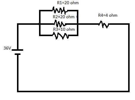
Here, the resistors
The resistor which provides the maximum current is
Conclusion:
Thus,
(b)
The resistor with maximum voltage drop.
Answer to Problem 5TP
Each of the resistor connected in parallel have the maximum voltage drop.
Explanation of Solution
Given:
Parallel combination of two
Source voltage =
Calculations:
With the given information, following circuit diagram can be drawn:
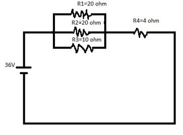
Here, the resistors
To find the voltage drop in the above circuit, compare the voltage across of
So, for finding the voltage drop, find the equivalent resistance separately as follows:
Conclusion:
Thus, the equivalent resistance of
(c)
The power dissipated in each of the resistor and total power dissipated in all resistor.
Answer to Problem 5TP
20 W in each
Output power source = 144 W.
Yes, they are equal as per law of conservation of energy.
Explanation of Solution
Given:
Parallel combination of two
Source voltage =
Calculations:
With the given information, following circuit diagram can be drawn:
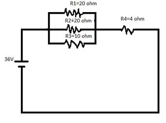
Here, the resistors
The voltage source is
To find the power dissipated in each of the resistor and the total power dissipated in each of the resistor, follow some steps one by one as below:
- Find the equivalent resistance and then find the total current.
- Voltage across parallel combination of resistance.
- Calculate the power dissipated in each resistor are:
- Total power dissipated in all the resistor.
- Find the total power output of the source as follows:
Conclusion:
The power dissipated of all the resistor and the total power output source are equal by the law of conservation of energy.
(e)
The values of all the resistors and the source voltage are doubled.
Answer to Problem 5TP
No effect.
Explanation of Solution
Given:
Parallel combination of two
Source voltage =
Calculations:
With the given information, following circuit diagram can be drawn:

Here, the resistors
If the values of all the resistors and the source voltage are doubled, then there would be no effect on the current.
Want to see more full solutions like this?
Chapter 21 Solutions
COLLEGE PHYSICS


- You have a summer internship at NASA and are working on plans for a new space station to be launched into orbit around the Earth. The design of the space station is shown. It is to be constructed in the shape of a hollow ring of mass 58,500 kg. The structures other than the ring shown in the figure have negligible mass compared to the ring. Members of the crew will walk on a deck formed by the inner surface of the outer cylindrical wall of the ring, with radius r = 125 m. The thickness of the ring is very small compared to the radius, so we can model the ring as a hoop. At rest when constructed, the ring is to be set rotating about its axis so that the people standing inside on this deck experience an effective free-fall acceleration equal to g. The rotation is achieved by firing two small rockets attached tangentially to opposite points on the rim of the ring. Your supervisor asks you to determine the following: (a) the time interval during which the rockets must be fired if each…arrow_forwardThe polar ice caps have a combined mass of about 2.65 × 10¹⁹ kg. If all of the ice in the polar ice caps melted, by how much time would the length of a day (Earth's rotational period) change? For simplicity, assume each ice cap is an identical thin solid disk with a radius of 7.20 x 10⁵ m. Find the change both in seconds and as a percentage of duration of a day. change in time percent change (No Response) s (No Response) %arrow_forward. A space probe in outer space has a gyroscope within it used for rotation and stabilization. The moment of inertia of the gyroscope is I = 17.5 kg m² about the axis of the gyroscope, and the moment of inertia of the rest of the space probe is I = 5.00 × 10⁵ kg • m² about the same axis. Initially both the space probe and gyroscope are not rotating. The gyroscope is then switched on and it nearly instantly starts rotating at an angular speed of 110 rad/s. How long (in s) should the gyroscope operate at this speed in order to change the space probe's orientation by 24.0°? (No Response) sarrow_forward
- Solve thisarrow_forwardWalking with a steady cadence is very important for covering long distances efficiently. How we place our feet, and how quickly we walk, also depends on the roughness of the surface we are walking upon and on the slope of the surface: we walk carefully on slippery surfaces, and take smaller steps when hiking up a hill. When we are walking at constant speed in a fixed direction, the horizontal and vertical components of the acceleration of our center of mass must be zero. In addition, the sum of torques about the body's center of mass must also be zero. Consider the situation shown in the figure below. ALMA XCM Х СМ XCM XCM XCM We can model the walking gait of a person as a swing of the front leg and torso about the point where the front foot is planted (shown with a red circle in the figure) and a rotation of the trailing leg about the center of mass (CM) of the person. If each leg of this 78.0 kg person is 85.0 cm long and has a mass of 13.8 kg, and 0; = 0₁ = 20.0°, what is the…arrow_forwardYou are attending a county fair with your friend from your physics class. While walking around the fairgrounds, you discover a new game of skill. A thin rod of mass M = 0.550 kg and length l = 2.80 m hangs from a friction-free pivot at its upper end as shown in the figure. Pivot Velcro M Incoming Velcro-covered ball m The front surface of the rod is covered with Velcro. You are to throw a Velcro-covered ball of mass m = 1.20 kg at the rod in an attempt to make it swing backward and rotate all the way across the top. The ball must stick to the rod at all times after striking it. If you cause the rod to rotate over the top position (that is, rotate 180° opposite of its starting position), you win a stuffed animal. Your friend volunteers to try his luck. He feels that the most torque would be applied to the rod by striking it at its lowest end. While he prepares to aim at the lowest point on the rod, you calculate how fast he must throw the ball to win the stuffed animal with this…arrow_forward
- A hanging weight, with a mass of m₁ = 0.365 kg, is attached by a rope to a block with mass m₂ = 0.835 kg as shown in the figure below. The rope goes over a pulley with a mass of M = 0.350 kg. The pulley can be modeled as a hollow cylinder with an inner radius of R₁ = 0.0200 m, and an outer radius of R2 = 0.0300 m; the mass of the spokes is negligible. As the weight falls, the block slides on the table, and the coefficient of kinetic friction between the block and the table is μ = 0.250. At the instant shown, the block is moving with a velocity of v; = 0.820 m/s toward the pulley. Assume that the pulley is free to spin without friction, that the rope does not stretch and does not slip on the pulley, and that the mass of the rope is negligible. R₂ R₁ Mo mi (a) Using energy methods, find the speed of the block (in m/s) after it has moved a distance of 0.700 m away from the initial position shown. (No Response) m/s (b) What is the angular speed of the pulley (in rad/s) after the block has…arrow_forwardA stiff, thin, metal rod with negligible mass is free to rotate in a vertical plane about pivot point P, as shown in the figure below. The rod has three small beads (labeled 1, 2, and 3 in the figure), all with the same mass m, attached to it as shown. The rod is held horizontally and then released from rest at time t = 0. Find all results below in terms of the mass m, distance d, and acceleration due to gravity g. 1 P m m 2 2d 23 m 3 (a) What is the moment of inertia of the system of three particles about the pivot point P? I= (No Response) (b) What is the net torque magnitude about point P at t = 0? Tnet = (No Response) (c) What is the angular acceleration of the system about point P at t = 0? magnitude direction α = (No Response) (No Response) (d) What is the linear acceleration of bead 3 at t = 0? magnitude a = (No Response) direction (No Response) (e) What is the maximum kinetic energy of the system? K = (No Response) max (f) What is the maximum angular speed about point P…arrow_forwardDuring a concentric loading of the quadriceps muscle in the upper leg, an athlete extends his lower leg from a vertical position (see figure (a)) to a fully extended horizontal position (see figure (b)) at a constant angular speed of 45.0° per second. Two of the four quadriceps muscles, the vastis intermedius and the rectus femoris, terminate at the patellar tendon which is attached to the top of the tibia in the lower leg. The distance from the point of attachment of the patellar tendon to the rotation axis of the tibia relative to the femur is 4.10 cm in this athlete. a b (a) The two quadriceps muscles can exert a maximum force of 225 N through the patellar tendon. This force is applied at an angle of 25.0° to the section of the tibia between the attachment point and the rotation axis. What is the torque (in N m) exerted by the muscle on the lower leg during this motion? (Enter the magnitude.) (No Response) N⚫ m (b) What is the power (in W) generated by the athlete during the motion?…arrow_forward
- A 3.1-kg sphere is suspended by a cord that passes over a 1.6-kg pulley of radius 3.3 cm. The cord is attached to a spring whose force constant is k = 86 N/m as in the figure below. Assume the pulley is a solid disk. www m (a) If the sphere is released from rest with the spring unstretched, what distance does the sphere fall through before stopping? (No Response) m (b) Find the speed of the sphere after it has fallen 25 cm. (No Response) m/sarrow_forwardThe angular momentum vector of a precessing gyroscope sweeps out a cone as shown in the figure below. The angular speed of the tip of the angular momentum vector, called its precessional frequency, is given by @p = t/L, where is the magnitude of the torque on the gyroscope and L is the magnitude of its angular momentum. In the motion called precession of the equinoxes, the Earth's axis of rotation precesses about the perpendicular to its orbital plane with a period of 2.58 × 10⁴ yr. Model the Earth as a uniform sphere and calculate the torque on the Earth that is causing this precession. (No Response) N⚫ marrow_forwardA space station shaped like a giant wheel has a radius of 121 m and a moment of inertia of 5.12 × 10⁸ kg. m². A crew of 150 lives on the rim, and the station is rotating so that the crew experiences an apparent acceleration of 1g. When 100 people move to the center of the station for a union meeting, the angular speed changes. What apparent acceleration is experienced by the managers remaining at the rim? Assume that the average mass of each inhabitant is 65.0 kg. (No Response) m/s²arrow_forward

 Principles of Physics: A Calculus-Based TextPhysicsISBN:9781133104261Author:Raymond A. Serway, John W. JewettPublisher:Cengage Learning
 College PhysicsPhysicsISBN:9781938168000Author:Paul Peter Urone, Roger HinrichsPublisher:OpenStax College
 College PhysicsPhysicsISBN:9781305952300Author:Raymond A. Serway, Chris VuillePublisher:Cengage Learning
 College PhysicsPhysicsISBN:9781285737027Author:Raymond A. Serway, Chris VuillePublisher:Cengage Learning
 Physics for Scientists and Engineers, Technology ...PhysicsISBN:9781305116399Author:Raymond A. Serway, John W. JewettPublisher:Cengage Learning