Principles of Physics: A Calculus-Based Text, Hybrid (with Enhanced WebAssign Printed Access Card)
5th Edition
ISBN: 9781305586871
Author: Raymond A. Serway, John W. Jewett
Publisher: Cengage Learning
expand_more
expand_more
format_list_bulleted
Videos
Textbook Question
Chapter 21, Problem 41P
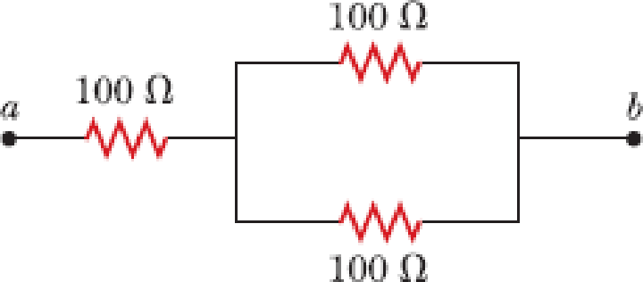
Three 100-Ω resistors are connected as shown in Figure P21.41 The maximum power that can safely be delivered to any one resistor is 25.0 W. (a) What is the maximum potential difference that can be applied to the terminals a and b? (b) For the voltage determined in part (a), what is the power delivered to each resistor? (c) What is the total power delivered to the combination of resistors?
Expert Solution & Answer
Want to see the full answer?
Check out a sample textbook solution
Students have asked these similar questions
Gg
Please show steps
A 3.0[μF] capacitor is initially charged to its maximum capacity. It is then connected in series to a 3.5[kΩ] resistor. How long will it take to discharge the capacitor to half its maximum charge?
Chapter 21 Solutions
Principles of Physics: A Calculus-Based Text, Hybrid (with Enhanced WebAssign Printed Access Card)
Ch. 21.1 - Consider positive and negative charges moving...Ch. 21.2 - Prob. 21.2QQCh. 21.2 - When does an incandescent lightbulb carry more...Ch. 21.5 - For the two incandescent lightbulbs shown in...Ch. 21.7 - Prob. 21.5QQCh. 21.7 - With the switch in the circuit of Figure 21.18a...Ch. 21.7 - Prob. 21.7QQCh. 21.9 - Consider the circuit in Figure 21.29 and assume...Ch. 21 - If the terminals of a battery with zero internal...Ch. 21 - Wire B has twice the length and twice the radius...
Ch. 21 - The current-versus-voltage behavior of a certain...Ch. 21 - Prob. 4OQCh. 21 - A potential difference of 1.00 V is maintained...Ch. 21 - Prob. 6OQCh. 21 - A metal wire of resistance R is cut into three...Ch. 21 - The terminals of a battery are connected across...Ch. 21 - Prob. 9OQCh. 21 - Two conducting wires A and B of the same length...Ch. 21 - When resistors with different resistances are...Ch. 21 - When operating on a 120-V circuit, an electric...Ch. 21 - Prob. 13OQCh. 21 - Prob. 14OQCh. 21 - In the circuit shown in Figure OQ21.15, each...Ch. 21 - Prob. 1CQCh. 21 - Prob. 2CQCh. 21 - Prob. 3CQCh. 21 - Referring to Figure CQ21.4, describe what happens...Ch. 21 - When the potential difference across a certain...Ch. 21 - Use the atomic theory of matter to explain why the...Ch. 21 - Prob. 7CQCh. 21 - (a) What advantage does 120-V operation offer over...Ch. 21 - Prob. 9CQCh. 21 - Prob. 10CQCh. 21 - If you were to design an electric heater using...Ch. 21 - Prob. 12CQCh. 21 - Prob. 13CQCh. 21 - Prob. 14CQCh. 21 - Why is it possible for a bird to sit on a...Ch. 21 - Prob. 1PCh. 21 - Prob. 2PCh. 21 - The quantity of charge q (in coulombs) that has...Ch. 21 - Prob. 4PCh. 21 - Prob. 5PCh. 21 - Figure P21.6 represents a section of a conductor...Ch. 21 - Prob. 7PCh. 21 - A 0.900-V potential difference is maintained...Ch. 21 - Prob. 9PCh. 21 - A lightbulb has a resistance of 240 when...Ch. 21 - Prob. 11PCh. 21 - Prob. 12PCh. 21 - While taking photographs in Death Valley on a day...Ch. 21 - Prob. 14PCh. 21 - If the current carried by a conductor is doubled,...Ch. 21 - Prob. 16PCh. 21 - Prob. 17PCh. 21 - Prob. 18PCh. 21 - Prob. 19PCh. 21 - Prob. 20PCh. 21 - Prob. 21PCh. 21 - Prob. 22PCh. 21 - Prob. 23PCh. 21 - Prob. 24PCh. 21 - A 100-W lightbulb connected to a 120-V source...Ch. 21 - Prob. 26PCh. 21 - Prob. 27PCh. 21 - Prob. 28PCh. 21 - A toaster is rated at 600 W when connected to a...Ch. 21 - Prob. 30PCh. 21 - Prob. 31PCh. 21 - Review. A well-insulated electric water heater...Ch. 21 - A battery has an emf of 15.0 V. The terminal...Ch. 21 - Two 1.50-V batterieswith their positive terminals...Ch. 21 - An automobile battery has an emf of 12.6 V and an...Ch. 21 - Prob. 36PCh. 21 - Prob. 37PCh. 21 - Prob. 38PCh. 21 - Consider the circuit shown in Figure P21.39. Find...Ch. 21 - Four resistors are connected to a battery as shown...Ch. 21 - Three 100- resistors are connected as shown in...Ch. 21 - Prob. 42PCh. 21 - Calculate the power delivered to each resistor in...Ch. 21 - Prob. 44PCh. 21 - The ammeter shown in Figure P21.45 reads 2.00 A....Ch. 21 - Prob. 46PCh. 21 - The circuit shown in Figure P21.47 is connected...Ch. 21 - In Figure P21.47, show how to add just enough...Ch. 21 - Taking R = 1.00 k and = 250 V in Figure P21.49,...Ch. 21 - For the circuit shown in Figure P21.50, we wish to...Ch. 21 - In the circuit of Figure P21.51, determine (a) the...Ch. 21 - Jumper cables are connected from a fresh battery...Ch. 21 - Prob. 53PCh. 21 - Prob. 54PCh. 21 - Prob. 55PCh. 21 - Prob. 56PCh. 21 - In the circuit of Figure P21.57, the switch S has...Ch. 21 - Prob. 58PCh. 21 - The circuit in Figure P21.59 has been connected...Ch. 21 - Assume that global lightning on the Earth...Ch. 21 - Prob. 61PCh. 21 - Prob. 62PCh. 21 - Prob. 63PCh. 21 - Prob. 64PCh. 21 - Prob. 65PCh. 21 - An oceanographer is studying how the ion...Ch. 21 - The values of the components in a simple series RC...Ch. 21 - Prob. 68PCh. 21 - Prob. 69PCh. 21 - Prob. 70PCh. 21 - The student engineer of a campus radio station...Ch. 21 - Prob. 72PCh. 21 - A battery has an emf and internal resistance r. A...Ch. 21 - Prob. 74PCh. 21 - Prob. 75PCh. 21 - Prob. 76PCh. 21 - Prob. 77P
Knowledge Booster


Learn more about
Need a deep-dive on the concept behind this application? Look no further. Learn more about this topic, physics and related others by exploring similar questions and additional content below.Similar questions
- Consider the circuit shown in Figure P26.24, where C1, = 6.00 F, C2 = 3.00 F. and V = 20.0 V. Capacitor C1 is first charged by closing switch S1. Switch S1 is then opened, and the charged capacitor is connected to the uncharged capacitor by closing Calculate (a) the initial charge acquired by C, and (b) the final charge on each capacitor.arrow_forwardThe circuit in Figure P21.59 has been connected for a long time. (a) What is the potential difference across the capacitor? (b) If the battery is disconnected from the circuit, over what time interval does the capacitor discharge to one-tenth its initial voltage?arrow_forwardA charge Q is placed on a capacitor of capacitance C. The capacitor is connected into the circuit shown in Figure P26.37, with an open switch, a resistor, and an initially uncharged capacitor of capacitance 3C. The switch is then closed, and the circuit comes to equilibrium. In terms of Q and C, find (a) the final potential difference between the plates of each capacitor, (b) the charge on each capacitor, and (c) the final energy stored in each capacitor. (d) Find the internal energy appearing in the resistor. Figure P26.37arrow_forward
- Draw two graphs of charge versus time on a capacitor. Draw one for charging an initially uncharged capacitor in series with a resistor, as in the circuit in Figure 21.38, starting from t = 0. Draw the other for discharging a capacitor through a resistor, as in the circuit in Figure 21.39, starting at t = 0, with an initial charge Q0. Show at least two intervals of t.arrow_forwardA Pairs of parallel wires or coaxial cables are two conductors separated by an insulator, so they have a capacitance. For a given cable, the capacitance is independent of the length if the cable is very long. A typical circuit model of a cable is shown in Figure P27.87. It is called a lumped-parameter model and represents how a unit length of the cable behaves. Find the equivalent capacitance of a. one unit length (Fig. P27.87A), b. two unit lengths (Fig. P27.87B), and c. an infinite number of unit lengths (Fig. P27.87C). Hint: For the infinite number of units, adding one more unit at the beginning does not change the equivalent capacitance.arrow_forwardFigure P18.26 shows a voltage divider, a circuit used to obtain a desired voltage Vout from a source voltage . Determine the required value of R2 if = 5.00 V, Vout = 1.50 V and R1 = 1.00 103 (Hint: Use Kirchhoff's loop rule, substituting Vout = IR2, to find the current. Then solve Ohms law for R2. Figure P18.26arrow_forward
- Consider the circuit shown in Figure P20.52, where C1 = 6.00 F, C2 = 3.00 F, and V = 20.0 V. Capacitor C1 is first charged by closing switch S1. Switch S1 is then opened, and the charged capacitor is connected to the uncharged capacitor by closing S2. Calculate (a) the initial charge acquired by C1 and (b) the final charge on each capacitor. Figure P20.52arrow_forward(a) Determine the equilibrium charge on the capacitor in the circuit of Figure P27.46 as a function of R. (b) Evaluate the charge when R = 10.0 . (c) Can the charge on the capacitor be zero? If so, for what value of R? (d) What is the maximum possible magnitude of the charge on the capacitor? For what value of R is it achieved? (c) Is it experimentally meaningful to take R = ? Explain your answer. If so, what charge magnitude does it imply? Figure P27.46arrow_forwardThe ammeter shown in Figure P21.45 reads 2.00 A. Find I1, I2, and . Figure P21.45arrow_forward
- Figure 21.55 shows how a bleeder resistor is used to discharge a capacitor after an electronic device is shut off allowing a person to work on the electronics with less risk of shock, (a) What is the time constant? (b) How long will it take to reduce the voltage on the capacitor to 0.250% (5% of 5%) of its full value once discharge begins? (c) If the capacitor is charged to a voltage V0through a 100-O resistance, calculate the time it takes to rise to 0.865V0(This is about two time constants.)arrow_forwardWhen resistors with different resistances are connected in parallel, which of the following must be the same for each resistor? Choose all correct answers, (a) potential difference (b) current (c) power delivered (d) charge entering each resistor in a given time interval (e) none of those answersarrow_forwardThree 100 resistors are connected as shown in the figure. The maximum power that can safely be delivered to any one resistor is 29.0 W. 100 Ω a 100 Ω ww 100 Ω (a) What is the maximum potential difference that can be applied to the terminals a and b? V (b) For the voltage determined in part (a), what is the power delivered to each resistor? resistor on the left W W resistor at the top of the loop resistor at the bottom of the loop W (c) What is the total power delivered to the combination of resistors? Warrow_forward
arrow_back_ios
SEE MORE QUESTIONS
arrow_forward_ios
Recommended textbooks for you
 Principles of Physics: A Calculus-Based TextPhysicsISBN:9781133104261Author:Raymond A. Serway, John W. JewettPublisher:Cengage Learning
 Physics for Scientists and Engineers: Foundations...PhysicsISBN:9781133939146Author:Katz, Debora M.Publisher:Cengage Learning
 Physics for Scientists and Engineers, Technology ...PhysicsISBN:9781305116399Author:Raymond A. Serway, John W. JewettPublisher:Cengage Learning
 Physics for Scientists and EngineersPhysicsISBN:9781337553278Author:Raymond A. Serway, John W. JewettPublisher:Cengage Learning
 Physics for Scientists and Engineers with Modern ...PhysicsISBN:9781337553292Author:Raymond A. Serway, John W. JewettPublisher:Cengage Learning
Principles of Physics: A Calculus-Based Text
Physics
ISBN:9781133104261
Author:Raymond A. Serway, John W. Jewett
Publisher:Cengage Learning
Physics for Scientists and Engineers: Foundations...
Physics
ISBN:9781133939146
Author:Katz, Debora M.
Publisher:Cengage Learning
Physics for Scientists and Engineers, Technology ...
Physics
ISBN:9781305116399
Author:Raymond A. Serway, John W. Jewett
Publisher:Cengage Learning
Physics for Scientists and Engineers
Physics
ISBN:9781337553278
Author:Raymond A. Serway, John W. Jewett
Publisher:Cengage Learning
Physics for Scientists and Engineers with Modern ...
Physics
ISBN:9781337553292
Author:Raymond A. Serway, John W. Jewett
Publisher:Cengage Learning
How To Solve Any Resistors In Series and Parallel Combination Circuit Problems in Physics; Author: The Organic Chemistry Tutor;https://www.youtube.com/watch?v=eFlJy0cPbsY;License: Standard YouTube License, CC-BY