
Concept explainers
Videos
a.
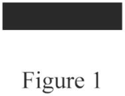
Draw the correct symbol for the description “Lighting panel”.
a.
Explanation of Solution
The symbol for the lighting panel is drawn and it is shown in Figure 1 as follows:
Conclusion:
Thus, the symbol for the given description is drawn.
b.
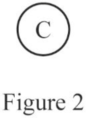
Draw the correct symbol for the description “Clock outlet”.
b.
Explanation of Solution
The symbol for the clock outlet is drawn and it is shown in Figure 2 as follows:
Conclusion:
Thus, the symbol for the given description is drawn.
c.
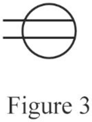
Draw the correct symbol for the description “Duplex outlet”.
c.
Explanation of Solution
The symbol for the duplex outlet is drawn and it is shown in Figure 3 as follows:
Conclusion:
Thus, the symbol for the given description is drawn.
d.
Draw the correct symbol for the description “Outside telephone”.
d.
Explanation of Solution
The symbol for the outside telephone is drawn and it is shown in Figure 4 as follows:

Conclusion:
Thus, the symbol for the given description is drawn.
e.
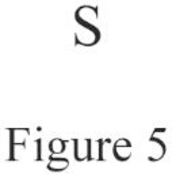
Draw the correct symbol for the description “Single-pole switch”.
e.
Explanation of Solution
The symbol for the single-pole switch is drawn and it is shown in Figure 5 as follows:
Conclusion:
Thus, the symbol for the given description is drawn.
f.
Draw the correct symbol for the description “Motor”.
f.
Explanation of Solution
The symbol for the motor is drawn and it is shown in Figure 6 as follows:

Conclusion:
Thus, the symbol for the given description is drawn.
g.
Draw the correct symbol for the description “Duplex outlet, split-wired”.
g.
Explanation of Solution
The symbol for the duplex outlet, split-wired is drawn and it is shown in Figure 7 as follows:
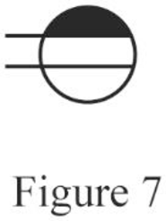
Conclusion:
Thus, the symbol for the given description is drawn.
h.
Draw the correct symbol for the description “Lampholder with pull switch”.
h.
Explanation of Solution
The symbol for the lampholder with pull switch is drawn and it is shown in Figure 8 as follows:
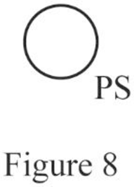
Conclusion:
Thus, the symbol for the given description is drawn.
i.
Draw the correct symbol for the description “Weatherproof outlet”.
i.
Explanation of Solution
The symbol for the weatherproof outlet is drawn and it is shown in Figure 9 as follows:
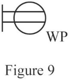
Conclusion:
Thus, the symbol for the given description is drawn.
j.
Draw the correct symbol for the description “Special-purpose outlet”.
j.
Explanation of Solution
The symbol for the special-purpose outlet is drawn and it is shown in Figure 10 as follows:
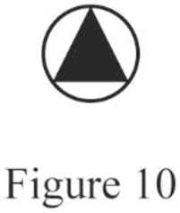
Conclusion:
Thus, the symbol for the given description is drawn.
k.
Draw the correct symbol for the description “fan outlet”.
k.
Explanation of Solution
The symbol for the fan outlet is drawn and it is shown in Figure 11 as follows:
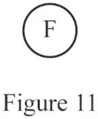
Conclusion:
Thus, the symbol for the given description is drawn.
l.
Draw the correct symbol for the description “Range outlet”.
l.
Explanation of Solution
The symbol for the range outlet is drawn and it is shown in Figure 12 as follows:
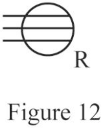
Conclusion:
Thus, the symbol for the given description is drawn.
m.
Draw the correct symbol for the description “Power panel”.
m.
Explanation of Solution
The symbol for the power panel is drawn and it is shown in Figure 13 as follows:
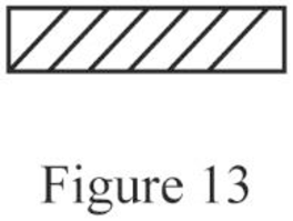
Conclusion:
Thus, the symbol for the given description is drawn.
n.
Draw the correct symbol for the description “3-way switch”.
n.
Explanation of Solution
The symbol for the 3-way switch is drawn and it is shown in Figure 14 as follows:
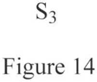
Conclusion:
Thus, the symbol for the given description is drawn.
o.
Draw the correct symbol for the description “Push button”.
o.
Explanation of Solution
The symbol for the push button is drawn and it is shown in Figure 15 as follows:
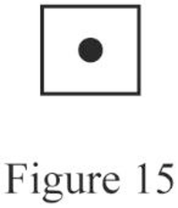
Conclusion:
Thus, the symbol for the given description is drawn.
p.
Draw the correct symbol for the description “Thermostat”.
p.
Explanation of Solution
The symbol for the thermostat is drawn and it is shown in Figure 16 as follows:
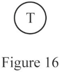
Conclusion:
Thus, the symbol for the given description is drawn.
q.
Draw the correct symbol for the description “Electric door opener”.
q.
Explanation of Solution
The symbol for the electric door opener is drawn and it is shown in Figure 17 as follows:
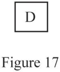
Conclusion:
Thus, the symbol for the given description is drawn.
r.
Draw the correct symbol for the description “Multioutlet assembly”.
r.
Explanation of Solution
The symbol for the multioutlet assembly is drawn and it is shown in Figure 18 as follows:
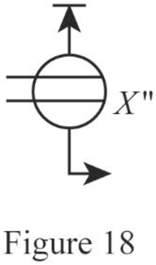
Where,
Conclusion:
Thus, the symbol for the given description is drawn.
Want to see more full solutions like this?
Chapter 2 Solutions
Electrical Wiring Residential


- please explain step by step how ti solve these problems and include good explanations. I am most confused with graphing. Thank you, I will give positive feedback. The rest of the questions to this problem are submitted as a new questions due to the multiple part limitarrow_forwardDon't use ai to answer I will report you answerarrow_forwardThis is the last two questions of a previous question I just sent. Please show step by step with clear explanations as to what to do for these questions. I am very confused. Thank you, I will give positive feedbackarrow_forward
 EBK ELECTRICAL WIRING RESIDENTIALElectrical EngineeringISBN:9781337516549Author:SimmonsPublisher:CENGAGE LEARNING - CONSIGNMENT