
Videos
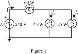
For the battery of bulbs (purely resistive) appearing in Fig. 20.48 :
a. Determine the total power dissipation.
b. Calculate the total reactive and apparent power.
c. Find the source current Is.
d. Calculate the resistance of each bulb for the specified operating conditions.
e. Determine the currents I1 and I2.
(a)
The total power dissipation.
Answer to Problem 1P
The total power dissipated is
Explanation of Solution
Calculation:
The given circuit diagram is shown in Figure 1.
The power dissipated in bulb 1 is
The total power dissipation is given by the sum of power dissipated in individual bulbs, that is,
Here,
Substitute
Conclusion:
Therefore, the total power dissipated is
(b)
The total reactive and apparent power.
Answer to Problem 1P
The reactive power dissipated in the bulbs is
Explanation of Solution
Calculation:
As the bulbs are purely resistive in nature therefore, the reactive power dissipated in bulb is zero that is,
The apparent power is given by,
Substitute
Conclusion:
Therefore, the reactive power dissipated in bulb is
(c)
The source current
Answer to Problem 1P
The source current
Explanation of Solution
Calculation:
The source voltage
The apparent power is given by,
Substitute
Conclusion:
Therefore, the source current
(d)
The resistance of each bulb.
Answer to Problem 1P
The resistance of bulb 1 is
Explanation of Solution
Calculation:
The power dissipated in first bulb is given by,
Substitute
The voltage
Substitute
From the figure 1 it can be seen that voltage
Substitute
The power dissipated in bulb 2 is given by,
Substitute
The power dissipated in bulb 3 is given by,
Substitute
Conclusion:
Therefore, the resistance of bulb 1 is
(e)
The current
Answer to Problem 1P
The current
Explanation of Solution
Calculation:
The value of current
Substitute
The current
Substitute
Conclusion:
Therefore, the current
Want to see more full solutions like this?
Chapter 20 Solutions
Introductory Circuit Analysis (13th Edition)
Additional Engineering Textbook Solutions
Vector Mechanics for Engineers: Statics and Dynamics
Concepts Of Programming Languages
Electric Circuits. (11th Edition)
Database Concepts (8th Edition)
BASIC BIOMECHANICS
Thermodynamics: An Engineering Approach


- R is 12 kΩ . Find the Thevenin equivalent resistance.arrow_forwardAssuming an ideal op-amp, design an inverting amplifier with a gain of 25 dB having the largest possible input resistance under the constraint of having to use resistors no larger than 90 kΩ. What's the input resist?arrow_forwardI need help with this problem and an explanation of the solution for the image described below. (Introduction to Signals and Systems)arrow_forward
- I hope the solution is on paper and not artificial intelligence. The subject is control systemarrow_forwardI hope the solution is on paper and not artificial intelligence.arrow_forwardVs R1 R2 ww ww 21x R3 Define the Thevenin equivalent of the above circuit where R1= 10 52, R2= 30 S2, R3 = 30 12, Vs = 70 V. VThevenin Number V RThevenin = Number Ωarrow_forward
- R1 ww + R3 15+ www R2 R4 ww With the circuit diagram shown above and the values of the circuit elements listed below, find i1, 12, v1, and v2. Is = 10A, R1 = 7 ohms, R2 = 9 ohms, R3 = 7 ohms, R4 = 8 ohms (a) i1 = Number A (b) 12 = Number A (c) v1 = Number V (d) v2 = Number Varrow_forward15 ww 22 R2 ли i4 1+ V4 R1 ww R3 Solve for current i4 using superposition where R1 = 902, R2 = 36052, R3 = 360 V, and 15 = 5 A. 27052, V4 = i4 due to voltage source (V4) alone: Number A i4 due to current source (15) alone: Number A i4 = Numberarrow_forwardPV Array Va DC/DC Converter Control Circuit ис V R Fig. 2. Principle of using DC/DC converter to implement electronic load [2] 4.5 1.5 -0.5 SEPIC Converters in SOM 0 0.2 0.4 0.6 0.8 Time SEPIC Converters in SOM M 0 0.2 0.4 0.6 0.8 Time Current I-V Curve (a) 8888888 P-V Curve 0 20 40 60 80 Voltage 0 20 40 60 Voltage 80 (b) Fig. 3. Experimental results of I-V and P-V curves [2]arrow_forward
 Introductory Circuit Analysis (13th Edition)Electrical EngineeringISBN:9780133923605Author:Robert L. BoylestadPublisher:PEARSON
 Delmar's Standard Textbook Of ElectricityElectrical EngineeringISBN:9781337900348Author:Stephen L. HermanPublisher:Cengage Learning
 Programmable Logic ControllersElectrical EngineeringISBN:9780073373843Author:Frank D. PetruzellaPublisher:McGraw-Hill Education
 Fundamentals of Electric CircuitsElectrical EngineeringISBN:9780078028229Author:Charles K Alexander, Matthew SadikuPublisher:McGraw-Hill Education
 Electric Circuits. (11th Edition)Electrical EngineeringISBN:9780134746968Author:James W. Nilsson, Susan RiedelPublisher:PEARSON
 Engineering ElectromagneticsElectrical EngineeringISBN:9780078028151Author:Hayt, William H. (william Hart), Jr, BUCK, John A.Publisher:Mcgraw-hill Education,