
Videos
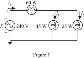
For the battery of bulbs (purely resistive) appearing in Fig. 20.48 :
a. Determine the total power dissipation.
b. Calculate the total reactive and apparent power.
c. Find the source current Is.
d. Calculate the resistance of each bulb for the specified operating conditions.
e. Determine the currents I1 and I2.
(a)
The total power dissipation.
Answer to Problem 1P
The total power dissipated is
Explanation of Solution
Calculation:
The given circuit diagram is shown in Figure 1.
The power dissipated in bulb 1 is
The total power dissipation is given by the sum of power dissipated in individual bulbs, that is,
Here,
Substitute
Conclusion:
Therefore, the total power dissipated is
(b)
The total reactive and apparent power.
Answer to Problem 1P
The reactive power dissipated in the bulbs is
Explanation of Solution
Calculation:
As the bulbs are purely resistive in nature therefore, the reactive power dissipated in bulb is zero that is,
The apparent power is given by,
Substitute
Conclusion:
Therefore, the reactive power dissipated in bulb is
(c)
The source current
Answer to Problem 1P
The source current
Explanation of Solution
Calculation:
The source voltage
The apparent power is given by,
Substitute
Conclusion:
Therefore, the source current
(d)
The resistance of each bulb.
Answer to Problem 1P
The resistance of bulb 1 is
Explanation of Solution
Calculation:
The power dissipated in first bulb is given by,
Substitute
The voltage
Substitute
From the figure 1 it can be seen that voltage
Substitute
The power dissipated in bulb 2 is given by,
Substitute
The power dissipated in bulb 3 is given by,
Substitute
Conclusion:
Therefore, the resistance of bulb 1 is
(e)
The current
Answer to Problem 1P
The current
Explanation of Solution
Calculation:
The value of current
Substitute
The current
Substitute
Conclusion:
Therefore, the current
Want to see more full solutions like this?
Chapter 20 Solutions
Introductory Circuit Analysis (13th Edition)
Additional Engineering Textbook Solutions
Vector Mechanics for Engineers: Statics and Dynamics
Concepts Of Programming Languages
Electric Circuits. (11th Edition)
Database Concepts (8th Edition)
BASIC BIOMECHANICS
Thermodynamics: An Engineering Approach


- Don't use ai to answer I will report you answerarrow_forwardanA fluid level control system includes a tank, a level sensor , a fluid source and an actuator to control fluid inflow. Show how the fluid level could be digitally controlled using a block diagramarrow_forwardsee the following imagearrow_forward
- Calculate A, B, C, and D constants, sending end voltage and sending end current of a 3-phase, 50-Hz overhead transmission line 100 km long has the following constants Resistance/km/phase = 0.1, Inductive reactance/km/phase 0.20, Capacitive susceptance/km/phase = 0.04 x 10 siemen. when supplying a balanced load of 10,000 kW at 66 kV, p.f. 0-8 lagging. Use nominal T method. andarrow_forwardDon't use ai to answer I will report you answerarrow_forwardNO AI PLEASE WILL REJECTarrow_forward
- NO AI PLEASE WILL REJECTarrow_forwardDon't use ai to answer I will report you answer. Please give explanation for both correct options and incorrectarrow_forward14:00 APP Voi) 5G 鼷浴醵郯興47% atheva.cc/index/index/index.html The Most Trusted, Secure, Fast, Reliable Cryptocurrency Exchange Get started with the easiest and most secure platform to buy, sell, trade, and earn Cryptocurrency Balance:1000.00 Recharge Withdraw Message About us BTC/USDT ETH/USDT EOS/USDT 83259.00 1841.46 83259.00 +1.02% +0.08% +1.02% Operating norms Symbol B BTC/USDT Latest price 24hFluctuation 83259.00 +1.02% ETH/USDT 1841.46 +0.08% B BTC/USD illı 83259.00 +1.02% Home Markets Trade Record Mine О <arrow_forward
 Introductory Circuit Analysis (13th Edition)Electrical EngineeringISBN:9780133923605Author:Robert L. BoylestadPublisher:PEARSON
 Delmar's Standard Textbook Of ElectricityElectrical EngineeringISBN:9781337900348Author:Stephen L. HermanPublisher:Cengage Learning
 Programmable Logic ControllersElectrical EngineeringISBN:9780073373843Author:Frank D. PetruzellaPublisher:McGraw-Hill Education
 Fundamentals of Electric CircuitsElectrical EngineeringISBN:9780078028229Author:Charles K Alexander, Matthew SadikuPublisher:McGraw-Hill Education
 Electric Circuits. (11th Edition)Electrical EngineeringISBN:9780134746968Author:James W. Nilsson, Susan RiedelPublisher:PEARSON
 Engineering ElectromagneticsElectrical EngineeringISBN:9780078028151Author:Hayt, William H. (william Hart), Jr, BUCK, John A.Publisher:Mcgraw-hill Education,