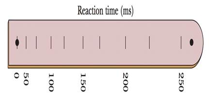
Figure 2-45 shows a simple device for measuring your reaction time. It consists of a cardboard strip marked with a scale and two large dots. A friend holds the strip vertically, with thumb and forefinger at the dot on the right in Fig. 2-45. You then position your thumb and forefinger at the other dot (on the left in Fig. 2-45), being careful not to touch the strip. Your friend releases the strip, and you try to pinch it as soon as possible after you see it begin to fall. The mark at the place where you pinch the strip gives your reaction time. (a) How far from the lower dot should you place the 50.0 ms mark? How much higher should you place the marks for (b) 100, (c) 150, (d) 200, and (e) 250 ms? (For example, should the 100 ms marker be 2 times as far from the dot as the 50 ms marker? If so, give an answer of 2 times. Can you find any pattern in the answers?)
Figure 2-45 shows a simple device for measuring your reaction time. It consists of a cardboard strip marked with a scale and two large dots. A friend holds the strip vertically, with thumb and forefinger at the dot on the right in Fig. 2-45. You then position your thumb and forefinger at the other dot (on the left in Fig. 2-45), being careful not to touch the strip. Your friend releases the strip, and you try to pinch it as soon as possible after you see it begin to fall. The mark at the place where you pinch the strip gives your reaction time. (a) How far from the lower dot should you place the 50.0 ms mark? How much higher should you place the marks for (b) 100, (c) 150, (d) 200, and (e) 250 ms? (For example, should the 100 ms marker be 2 times as far from the dot as the 50 ms marker? If so, give an answer of 2 times. Can you find any pattern in the answers?)
Figure 2-45 shows a simple device for measuring your reaction time. It consists of a cardboard strip marked with a scale and two large dots. A friend holds the strip vertically, with thumb and forefinger at the dot on the right in Fig. 2-45. You then position your thumb and forefinger at the other dot (on the left in Fig. 2-45), being careful not to touch the strip. Your friend releases the strip, and you try to pinch it as soon as possible after you see it begin to fall. The mark at the place where you pinch the strip gives your reaction time. (a) How far from the lower dot should you place the 50.0 ms mark? How much higher should you place the marks for (b) 100, (c) 150, (d) 200, and (e) 250 ms? (For example, should the 100 ms marker be 2 times as far from the dot as the 50 ms marker? If so, give an answer of 2 times. Can you find any pattern in the answers?)
For each of the actions depicted below, a magnet and/or metal loop moves with velocity v→ (v→ is constant and has the same magnitude in all parts). Determine whether a current is induced in the metal loop. If so, indicate the direction of the current in the loop, either clockwise or counterclockwise when seen from the right of the loop. The axis of the magnet is lined up with the center of the loop. For the action depicted in (Figure 5), indicate the direction of the induced current in the loop (clockwise, counterclockwise or zero, when seen from the right of the loop). I know that the current is clockwise, I just dont understand why. Please fully explain why it's clockwise, Thank you
A planar double pendulum consists of two point masses \[m_1 = 1.00~\mathrm{kg}, \qquad m_2 = 1.00~\mathrm{kg}\]connected by massless, rigid rods of lengths \[L_1 = 1.00~\mathrm{m}, \qquad L_2 = 1.20~\mathrm{m}.\]The upper rod is hinged to a fixed pivot; gravity acts vertically downward with\[g = 9.81~\mathrm{m\,s^{-2}}.\]Define the generalized coordinates \(\theta_1,\theta_2\) as the angles each rod makes with thedownward vertical (positive anticlockwise, measured in radians unless stated otherwise).At \(t=0\) the system is released from rest with \[\theta_1(0)=120^{\circ}, \qquad\theta_2(0)=-10^{\circ}, \qquad\dot{\theta}_1(0)=\dot{\theta}_2(0)=0 .\]Using the exact nonlinear equations of motion (no small-angle or planar-pendulumapproximations) and assuming the rods never stretch or slip, determine the angle\(\theta_2\) at the instant\[t = 10.0~\mathrm{s}.\]Give the result in degrees, in the interval \((-180^{\circ},180^{\circ}]\).
What are the expected readings of the ammeter and voltmeter for the circuit in the figure below? (R = 5.60 Ω, ΔV = 6.30 V)
ammeter
I =
Applications and Investigations in Earth Science (9th Edition)
Knowledge Booster
Learn more about
Need a deep-dive on the concept behind this application? Look no further. Learn more about this topic, physics and related others by exploring similar questions and additional content below.


 Classical Dynamics of Particles and SystemsPhysicsISBN:9780534408961Author:Stephen T. Thornton, Jerry B. MarionPublisher:Cengage Learning
 Principles of Physics: A Calculus-Based TextPhysicsISBN:9781133104261Author:Raymond A. Serway, John W. JewettPublisher:Cengage Learning
 College PhysicsPhysicsISBN:9781285737027Author:Raymond A. Serway, Chris VuillePublisher:Cengage Learning
 College PhysicsPhysicsISBN:9781305952300Author:Raymond A. Serway, Chris VuillePublisher:Cengage Learning
 Physics for Scientists and EngineersPhysicsISBN:9781337553278Author:Raymond A. Serway, John W. JewettPublisher:Cengage Learning
 Physics for Scientists and Engineers with Modern ...PhysicsISBN:9781337553292Author:Raymond A. Serway, John W. JewettPublisher:Cengage Learning