EBK FUNDAMENTALS OF APPLIED ELECTROMAGN
7th Edition
ISBN: 8220100663659
Author: ULABY
Publisher: PEARSON
expand_more
expand_more
format_list_bulleted
Concept explainers
Textbook Question
Chapter 2, Problem 50P
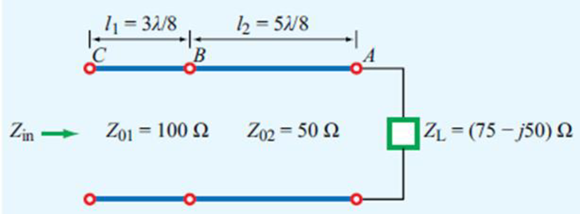
Use the Smith chart to determine the input impedance Zin of the two-line configuration shown in Fig. P2.50.

Figure P2.50 Circuit for Problem 2.50.
Expert Solution & Answer
Want to see the full answer?
Check out a sample textbook solution
Students have asked these similar questions
2 Find Inverse Fourier transform of
F(jw)
=
2w
-16+w2, and plot the f(t).
Need Handwritten Solution. Do not use chatgpt or AI
Solve by pen & paper without using chatgpt or AI
Mesh analysis
Chapter 2 Solutions
EBK FUNDAMENTALS OF APPLIED ELECTROMAGN
Ch. 2.2 - What is a transmission line? When should...Ch. 2.2 - Prob. 2CQCh. 2.2 - What constitutes a TEM transmission line?Ch. 2.2 - Prob. 4CQCh. 2.2 - Prob. 1ECh. 2.2 - Calculate the transmission line parameters at 1...Ch. 2.4 - Verify that Eq. (2.26a) indeed provides a solution...Ch. 2.4 - A two-wire air line has the following line...Ch. 2.6 - The attenuation constant represents ohmic losses....Ch. 2.6 - How is the wavelength of the wave traveling on...
Ch. 2.6 - Prob. 7CQCh. 2.6 - What is a standing-wave pattern? Why is its period...Ch. 2.6 - Prob. 9CQCh. 2.6 - For a lossless transmission line, = 20.7 cm at 1...Ch. 2.6 - A lossless transmission line uses a dielectric...Ch. 2.6 - Prob. 7ECh. 2.6 - Prob. 8ECh. 2.6 - Prob. 10ECh. 2.6 - A 140 lossless line is terminated in a load...Ch. 2.8 - What is the difference between the characteristic...Ch. 2.8 - What is a quarter-wave transformer? How can it be...Ch. 2.8 - Prob. 12CQCh. 2.8 - Prob. 13CQCh. 2.8 - if the input impedance of a lossless line is...Ch. 2.8 - Prob. 12ECh. 2.8 - A 300 feedline is to be connected to a 3 m long,...Ch. 2.9 - According to Eq. (2.102b), the instantaneous value...Ch. 2.9 - Prob. 16CQCh. 2.9 - What fraction of the incident power is delivered...Ch. 2.9 - Prob. 18CQCh. 2.9 - For a 50 lossless transmission line terminated in...Ch. 2.9 - For the line of Exercise 2-14, what is the...Ch. 2.10 - The outer perimeter of the Smith chart represents...Ch. 2.10 - What is an SWR circle? What quantities are...Ch. 2.10 - What line length corresponds to one complete...Ch. 2.10 - Which points on the SWR circle correspond to...Ch. 2.10 - Prob. 23CQCh. 2.10 - Use the Smith chart to find the values of ...Ch. 2.11 - Prob. 24CQCh. 2.11 - Prob. 25CQCh. 2.12 - What is transient analysis used for?Ch. 2.12 - Prob. 28CQCh. 2.12 - What is the difference between the bounce diagram...Ch. 2 - A transmission line of length l connects a load to...Ch. 2 - Show that the transmission-line model shown in...Ch. 2 - A 1 GHz parallel-plate transmission line consists...Ch. 2 - For the parallel-plate transmission line of...Ch. 2 - In addition to not dissipating power, a lossless...Ch. 2 - For a distortionless line [see Problem 2.13] with...Ch. 2 - Prob. 15PCh. 2 - A transmission line operating at 125 MHz has Z0 =...Ch. 2 - Prob. 17PCh. 2 - Polyethylene with r=2.25 is used as the insulating...Ch. 2 - Prob. 20PCh. 2 - Prob. 21PCh. 2 - Prob. 22PCh. 2 - Prob. 23PCh. 2 - A 50 lossless line terminated in a purely...Ch. 2 - Prob. 26PCh. 2 - Prob. 27PCh. 2 - Prob. 29PCh. 2 - Prob. 30PCh. 2 - Two half-wave dipole antennas, each with an...Ch. 2 - Prob. 34PCh. 2 - For the lossless transmission line circuit shown...Ch. 2 - A lossless transmission line is terminated in a...Ch. 2 - The input impedance of a 31 cm long lossless...Ch. 2 - FM broadcast station uses a 300 transmission line...Ch. 2 - A generator with Vg=300 V and Zg = 50 is...Ch. 2 - If the two-antenna configuration shown in Fig....Ch. 2 - For the circuit shown in Fig. P2.44, calculate the...Ch. 2 - The circuit shown in Fig. P2.45 consists of a 100 ...Ch. 2 - An antenna with a load impedance ZL=(75+j25) is...Ch. 2 - Prob. 47PCh. 2 - Use the Smith chart to determine the input...Ch. 2 - Prob. 52PCh. 2 - A lossless 50 transmission line is terminated in...Ch. 2 - A lossless 50 transmission line is terminated in...Ch. 2 - Use the Smith chart to find yL if zL = 1.5 j0.7.Ch. 2 - Prob. 59PCh. 2 - Prob. 62PCh. 2 - Determine Zin of the feed line shown in Fig....Ch. 2 - Prob. 73PCh. 2 - A 25 antenna is connected to a 75 lossless...Ch. 2 - Prob. 75PCh. 2 - Prob. 76PCh. 2 - Prob. 77PCh. 2 - In response to a step voltage, the voltage...Ch. 2 - Suppose the voltage waveform shown in Fig. P2.77...Ch. 2 - For the circuit of Problem 2.80, generate a bounce...Ch. 2 - In response to a step voltage, the voltage...
Knowledge Booster
Learn more about
Need a deep-dive on the concept behind this application? Look no further. Learn more about this topic, electrical-engineering and related others by exploring similar questions and additional content below.Similar questions
- 49. For the circuit below, what is the best connection of the capacitor to filte voltage? ბი DO A O BO wwwww wwwww M m H E LOADarrow_forward5.25. Determine the corner frequency resulting from Cin in Fig. 5.47(d). For simplicity, assume C₁ is a short circuit. TVDD C₁ M2 RF Vin H w - Vout Cin M₁arrow_forwardIn the below circuit, find out the value of equivalent Thevenin's voltage and Thevenin's resistance at the terminal. 2000 0.25 A 400 2 800 2 0.1 Aarrow_forward
- Q1: For the circuit shown in Figure-1, (a) Calculate the equivalent resistance of the circuit, RAB at the terminals A and B. [10] (b) When 50V dc source is switched at terminals A-B, solve for the voltage V₁ at the location shown. [10] 50V www 12Ω 10Ω 5Ω www www A + B 200 Figure-1 www 10Ω ww 25Ω 100arrow_forwarda. Write a PLC ladder diagram that allows the teacher to teach AND, OR, and XOR logic gates through using three PLC's digital input points and only one digital output point.arrow_forwardrately by PRACTICE 4.2 For the circuit of Fig. 4.5, compute the voltage across each curren source. 202 ww 3A 30 ww 4Ω S 50 www Reference node FIGURE 4.5 Ans: V3A =5.235 V; 7A = 11.47 V. 7 Aarrow_forward
- Q2) a) design and show me your steps to convert the following signal from continuous form to digital form: s(t)=3sin(3πt) -1 373 Colesarrow_forwardA sequence is defined by the relationship r[n] = [h[m]h[n+m]=hn*h-n where h[n] is a minimum-phase sequence and r[n]= 4 4 (u[n]+ 12" [n-1] 3 (a) Find R(z) and sketch the pole-zero diagram. (b) Determine the minimum-phase sequence h[n] to within a scale factor of ±1. Also, determine the z-transform H(z) of h[n].arrow_forwardusıng j-k and D flipflop design a counter that counts 0,2,1 again as shown below ın the tablearrow_forward
arrow_back_ios
SEE MORE QUESTIONS
arrow_forward_ios
Recommended textbooks for you
 Power System Analysis and Design (MindTap Course ...Electrical EngineeringISBN:9781305632134Author:J. Duncan Glover, Thomas Overbye, Mulukutla S. SarmaPublisher:Cengage Learning

Power System Analysis and Design (MindTap Course ...
Electrical Engineering
ISBN:9781305632134
Author:J. Duncan Glover, Thomas Overbye, Mulukutla S. Sarma
Publisher:Cengage Learning
How do Electric Transmission Lines Work?; Author: Practical Engineering;https://www.youtube.com/watch?v=qjY31x0m3d8;License: Standard Youtube License