
POWER SYS. ANALYSIS+DESIGN
6th Edition
ISBN: 9780357700907
Author: Glover
Publisher: INTER CENG
expand_more
expand_more
format_list_bulleted
Concept explainers
Videos
Textbook Question
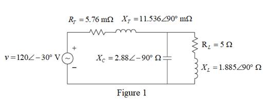
Chapter 2, Problem 2.8P
Consider the circuit shown in Figure 2.23 in time domain. Convert the entire circuit into phasor domain.
Expert Solution & Answer

Trending nowThis is a popular solution!

Students have asked these similar questions
15 OF 25 QUESTIONS REMAININ
Consider the following code. You want to print the array values in the div as an ordered list. What statement would you use to
replace the comment in the code below?
Two
J
// what statement goes here?
-
لبية للالكالا
const app = Vue.createApp({
data ((
return (
lunch: [
'Burrito',
'Soup',
'Pizza',
'Rice'
})
app.mount ('#app6')
-
-
Please answer JAVA OOP problem below:
Assume you have three data definition classes, Person, Student and Faculty. The Student and Faculty classes extend Person. Given the code snippet below, in Java, complete the method determinePersonTypeCount to print out how many Student and Faculty objects exist within the Person array. You may assume that each object within the Person[] is either referencing a Student or Faculty object.
public static void determinePersonTypeCount(Person[] people){
// Place your code here
}
Please answer JAVA OOP question below:
Consider the following relationship diagram between the Game and VideoGame data defintion classes.
Game has a constructor that takes in two parameters, title (String) and cost (double). The VideoGame constructor has an additional parameter, genre (String). In Java, efficiently write the constructors needed within the Game class and VideoGame classes.
Hint: Remember to think about the appropriate validation
Chapter 2 Solutions
POWER SYS. ANALYSIS+DESIGN
Ch. 2 - The rms value of v(t)=Vmaxcos(t+) is given by a....Ch. 2 - If the rms phasor of a voltage is given by V=12060...Ch. 2 - If a phasor representation of a current is given...Ch. 2 - Prob. 2.4MCQCh. 2 - Prob. 2.5MCQCh. 2 - Prob. 2.6MCQCh. 2 - Prob. 2.7MCQCh. 2 - Prob. 2.8MCQCh. 2 - Prob. 2.9MCQCh. 2 - The average value of a double-frequency sinusoid,...
Ch. 2 - The power factor for an inductive circuit (R-L...Ch. 2 - The power factor for a capacitive circuit (R-C...Ch. 2 - Prob. 2.13MCQCh. 2 - The instantaneous power absorbed by the load in a...Ch. 2 - Prob. 2.15MCQCh. 2 - With generator conyention, where the current...Ch. 2 - Consider the load convention that is used for the...Ch. 2 - Prob. 2.18MCQCh. 2 - The admittance of the impedance j12 is given by...Ch. 2 - Consider Figure 2.9 of the text, Let the nodal...Ch. 2 - The three-phase source line-to-neutral voltages...Ch. 2 - In a balanced three-phase Y-connected system with...Ch. 2 - In a balanced system, the phasor sum of the...Ch. 2 - Consider a three-phase Y-connected source feeding...Ch. 2 - For a balanced- load supplied by a balanced...Ch. 2 - A balanced -load can be converted to an...Ch. 2 - When working with balanced three-phase circuits,...Ch. 2 - The total instantaneous power delivered by a...Ch. 2 - The total instantaneous power absorbed by a...Ch. 2 - Under balanced operating conditions, consider the...Ch. 2 - One advantage of balanced three-phase systems over...Ch. 2 - While the instantaneous electric power delivered...Ch. 2 - Given the complex numbers A1=630 and A2=4+j5, (a)...Ch. 2 - Convert the following instantaneous currents to...Ch. 2 - The instantaneous voltage across a circuit element...Ch. 2 - For the single-phase circuit shown in Figure...Ch. 2 - A 60Hz, single-phase source with V=27730 volts is...Ch. 2 - (a) Transform v(t)=75cos(377t15) to phasor form....Ch. 2 - Let a 100V sinusoidal source be connected to a...Ch. 2 - Consider the circuit shown in Figure 2.23 in time...Ch. 2 - For the circuit shown in Figure 2.24, compute the...Ch. 2 - For the circuit element of Problem 2.3, calculate...Ch. 2 - Prob. 2.11PCh. 2 - The voltage v(t)=359.3cos(t)volts is applied to a...Ch. 2 - Prob. 2.13PCh. 2 - A single-phase source is applied to a...Ch. 2 - Let a voltage source v(t)=4cos(t+60) be connected...Ch. 2 - A single-phase, 120V(rms),60Hz source supplies...Ch. 2 - Consider a load impedance of Z=jwL connected to a...Ch. 2 - Let a series RLC network be connected to a source...Ch. 2 - Consider a single-phase load with an applied...Ch. 2 - A circuit consists of two impedances, Z1=2030 and...Ch. 2 - An industrial plant consisting primarily of...Ch. 2 - The real power delivered by a source to two...Ch. 2 - A single-phase source has a terminal voltage...Ch. 2 - A source supplies power to the following three...Ch. 2 - Consider the series RLC circuit of Problem 2.7 and...Ch. 2 - A small manufacturing plant is located 2 km down a...Ch. 2 - An industrial load consisting of a bank of...Ch. 2 - Three loads are connected in parallel across a...Ch. 2 - Prob. 2.29PCh. 2 - Figure 2.26 shows three loads connected in...Ch. 2 - Consider two interconnected voltage sources...Ch. 2 - Prob. 2.35PCh. 2 - Prob. 2.36PCh. 2 - Prob. 2.37PCh. 2 - Prob. 2.38PCh. 2 - Prob. 2.39PCh. 2 - A balanced three-phase 240-V source supplies a...Ch. 2 - Prob. 2.41PCh. 2 - A balanced -connected impedance load with (12+j9)...Ch. 2 - A three-phase line, which has an impedance of...Ch. 2 - Two balanced three-phase loads that are connected...Ch. 2 - Two balanced Y-connected loads, one drawing 10 kW...Ch. 2 - Three identical impedances Z=3030 are connected in...Ch. 2 - Two three-phase generators supply a three-phase...Ch. 2 - Prob. 2.48PCh. 2 - Figure 2.33 gives the general -Y transformation....Ch. 2 - Consider the balanced three-phase system shown in...Ch. 2 - A three-phase line with an impedance of...Ch. 2 - A balanced three-phase load is connected to a...Ch. 2 - What is a microgrid?Ch. 2 - What are the benefits of microgrids?Ch. 2 - Prob. CCSQCh. 2 - Prob. DCSQ
Knowledge Booster


Learn more about
Need a deep-dive on the concept behind this application? Look no further. Learn more about this topic, electrical-engineering and related others by exploring similar questions and additional content below.Similar questions
- In a shopping cart, there are various items, which can either belong to the category of household items or electronic items. The following UML diagram illustrates the relationship between items, household items, and electronic items. //Implementation Class public class ShoppingCart{ public static void main(String[] args){ final int MAX_ITEM = 50; Item cart = new Item[MAX_ITEM]; addItem(cart); // populate the item array printItem(cart); } } Considering that all the data definition classes and the implementation class are complete, which of the following Object-Oriented Programming (OOP) concepts do you need to use in the above context? i) Polymorphism ii) Method Overloading iii) Method Overriding iv) Dynamic Binding v) Abstract Class Explain, using course terminology, how you would use any of the above concepts to model the given scenario.arrow_forwardAnswer this JAVA OOP question below: An Employee has a name, employee ID, and department. An Employee object must be created with all its attributes. The UML diagram is provided below: - name: String - employeeId: String - department: String + Employee(name: String, employeeId: String, department: String) + setName(name: String): void + setEmployeeId(employeeId: String): void + setDepartment(department: String): void + getName(): String + getEmployeeId(): String + getDepartment(): String + toString(): String A faculty is an Employee with an additional field String field: rank public class TestImplementation{ public static void main(String[] args){ Employee[] allEmployee = new Employee[100]; // create an employee object with name Tom Evan, employee ID 001 and department IST and store it in allEmployee // create a faculty object with name Adam Scott, employee ID 002, department IST and rank Professor and store it in allEmployee } }arrow_forwardPlease answer this JAVA OOP question that is given below: An Employee has a name, employee ID, and department. An Employee object must be created with all its attributes. The UML diagram is provided below: - name: String - employeeId: String - department: String + Employee(name: String, employeeId: String, department: String) + setName(name: String): void + setEmployeeId(employeeId: String): void + setDepartment(department: String): void + getName(): String + getEmployeeId(): String + getDepartment(): String + toString(): String A faculty is an Employee with an additional field String field: rank Assuming the Employee class is fully implemented, define a Professor class in Java with the following: A toString() method that includes both the inherited attributes and the specializationarrow_forward
- Please answer JAVA OOP question below: An Employee has a name, employee ID, and department. An Employee object must be created with all its attributes. The UML diagram is provided below: - name: String - employeeId: String - department: String + Employee(name: String, employeeId: String, department: String) + setName(name: String): void + setEmployeeId(employeeId: String): void + setDepartment(department: String): void + getName(): String + getEmployeeId(): String + getDepartment(): String + toString(): String A faculty is an Employee with an additional field String field: rank Assuming the Employee class is fully implemented, define a Professor class in Java with the following: Instance variable(s) A Constructorarrow_forwardDevelop a C++ program that execute the operation as stated by TM for addition of two binary numbers (see attached image). Your code should receive two binary numbers and output the resulting sum (also in binary). Make sure your code mimics the TM operations (dealing with the binary numbers as a string of characters 1 and 0, and following the logic to increase the first number and decreasing the second one. Try your TM for the following examples: 1101 and 101, resulting 10010; and 1101 and 11, resulting 10000.arrow_forwardI need to define and discuss the uses of one monitoring or troubleshooting tool in Windows Server 2019. thank youarrow_forward
- I would likr toget help with the following concepts: - Windows Server features - Windows Server versus Windows 10 used as a client-server networkarrow_forwardI need to define and discuss the uses of one monitoring or troubleshooting tool in Windows Server 2019. thank youarrow_forwardWhy is planning for the retirement system and transition critical?arrow_forward
arrow_back_ios
SEE MORE QUESTIONS
arrow_forward_ios
Recommended textbooks for you
 Systems ArchitectureComputer ScienceISBN:9781305080195Author:Stephen D. BurdPublisher:Cengage Learning
 Operations Research : Applications and AlgorithmsComputer ScienceISBN:9780534380588Author:Wayne L. WinstonPublisher:Brooks Cole
 Principles of Information Systems (MindTap Course...Computer ScienceISBN:9781285867168Author:Ralph Stair, George ReynoldsPublisher:Cengage Learning
 New Perspectives on HTML5, CSS3, and JavaScriptComputer ScienceISBN:9781305503922Author:Patrick M. CareyPublisher:Cengage Learning
 Programming Logic & Design ComprehensiveComputer ScienceISBN:9781337669405Author:FARRELLPublisher:CengageNp Ms Office 365/Excel 2016 I NtermedComputer ScienceISBN:9781337508841Author:CareyPublisher:Cengage
Systems Architecture
Computer Science
ISBN:9781305080195
Author:Stephen D. Burd
Publisher:Cengage Learning
Operations Research : Applications and Algorithms
Computer Science
ISBN:9780534380588
Author:Wayne L. Winston
Publisher:Brooks Cole
Principles of Information Systems (MindTap Course...
Computer Science
ISBN:9781285867168
Author:Ralph Stair, George Reynolds
Publisher:Cengage Learning
New Perspectives on HTML5, CSS3, and JavaScript
Computer Science
ISBN:9781305503922
Author:Patrick M. Carey
Publisher:Cengage Learning
Programming Logic & Design Comprehensive
Computer Science
ISBN:9781337669405
Author:FARRELL
Publisher:Cengage
Np Ms Office 365/Excel 2016 I Ntermed
Computer Science
ISBN:9781337508841
Author:Carey
Publisher:Cengage
Maximum Power Transfer Theorem Using Nodal Analysis & Thevenin Equivalent Circuits; Author: The Organic Chemistry Tutor;https://www.youtube.com/watch?v=8CA6ZNXgI-Y;License: Standard Youtube License