
EBK THE ANALYSIS AND DESIGN OF LINEAR C
8th Edition
ISBN: 9781119140320
Author: Toussaint
Publisher: VST
expand_more
expand_more
format_list_bulleted
Concept explainers
Videos
Textbook Question
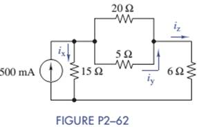
Chapter 2, Problem 2.62P
Find
Expert Solution & Answer
Want to see the full answer?
Check out a sample textbook solution
Students have asked these similar questions
Explain what is meant by an electric dipole antenna, sketch its radiation pattern, state itsdirectivity and describe its main applications
Estimate the length required for a half-waveelectric dipole antenna for transmitting/receiving EM waves at 800 MHz (this is in the UHFbandwidth of 470 to 860 MHz, used for UK TV transmissions).
If the voltage waveform in Fig. 6.68 is applied to a 50-mH inductor, find the inductor current i(1). Assume i(0) = 0.
Chapter 2 Solutions
EBK THE ANALYSIS AND DESIGN OF LINEAR C
Ch. 2 - Prob. 2.1PCh. 2 - The voltage across a particular resistor is 8.60 V...Ch. 2 - You can choose to connect either a 4.7-k resistor...Ch. 2 - A model railroader wants to be able to...Ch. 2 - A 100-k resistor dissipates 50mW. Find the current...Ch. 2 - The conductance of a particular semiconductor...Ch. 2 - In Figure P2—7 the resistor dissipates 25 mW. Find...Ch. 2 - In Figure P2—8 find Rx and the power supplied by...Ch. 2 - A resistor found in the lab has three orange...Ch. 2 - The iv characteristic of a nonlinear resistor is...
Ch. 2 - A 100-k resistor has a power rating of 0.25 W....Ch. 2 - A certain type of film resistor is available with...Ch. 2 - Figure P2—13 shows the circuit symbol for a class...Ch. 2 - A thermistor is a temperature-sensing element...Ch. 2 - In Figure P2-15i2=6A and i3=2A. Find i1 and i4.Ch. 2 - In Figure P2-16 determine which elements are in...Ch. 2 - For the circuit in Figure P2—17: Identify the...Ch. 2 - In Figure P2-17 i2=30mA and i4=20mA. Find i1 and...Ch. 2 - For the circuit in Figure P2—19: Identify the...Ch. 2 - In Figure P2-19 v2=20V,v3=20V, and v4=6V. Find...Ch. 2 - In many circuits the ground is often the metal...Ch. 2 - The circuit in figure P2-22 is organized around...Ch. 2 - Are any of the elements in Figure P2-23 in series...Ch. 2 - Are any of the elements in Figure P2-24 in series...Ch. 2 - Use the passive sign convention to assign voltage...Ch. 2 - If a wire is connected between nodes B and C in...Ch. 2 - The KCL equations for a three-node circuit are as...Ch. 2 - For the circuit in Figure P2—28, write a complete...Ch. 2 - For the circuit in Figure P2—29, write a complete...Ch. 2 - Find vx and ix in Figure P2-30. Compare the...Ch. 2 - A modeler wants to light his model building using...Ch. 2 - Find vx and ix in Figure P2-32.Ch. 2 - In Figure P2-33: Assign a voltage and current...Ch. 2 - Find vO in the circuit of Figure P2-34.Ch. 2 - Find the power provided by the source in Figure...Ch. 2 - Figure P2-36 shows a subcircuit connected to the...Ch. 2 - In Figure P2-37 ix=0.33mA. Find the value of R.Ch. 2 - Figure P2—38 shows a resistor with one terminal...Ch. 2 - Find the equivalent resistant REQ in Figure P2-39.Ch. 2 - Find the equivalent R EQ in Figure P2-40.Ch. 2 - Find the equivalent resistance REQ in Figure...Ch. 2 - Equivalent resistance is defined at a particular...Ch. 2 - Find REQ in Figure P2—43 when the switch is open....Ch. 2 - Find REQ between nodes A and B for each of the...Ch. 2 - Show how the circuit in Figure P2—45 could be...Ch. 2 - In Figure P2-46 find the equivalent resistance...Ch. 2 - In Figure P2-47 find the equivalent resistance...Ch. 2 - Select a value of RL in Figure P2-48 so that...Ch. 2 - Using no more than four 1-k resistors, show how...Ch. 2 - Do a source transformation at terminals A and B...Ch. 2 - For each of the circuits in Figure P2-51, find the...Ch. 2 - In Figure P2-52, the iv characteristic of network...Ch. 2 - Select the value of Rx in Figure P2-53 so that...Ch. 2 - Two 10-k potentiometers (a variable resistor whose...Ch. 2 - Select the value of R in Figure P2-55 so that...Ch. 2 - What is the range of REQ in Figure P2-56?Ch. 2 - Find the equivalent resistance between terminals A...Ch. 2 - Use voltage division in Figure P2-58 to find...Ch. 2 - Use voltage division in Figure P2-59 to obtain an...Ch. 2 - Use current division in Figure P2-60 to find...Ch. 2 - Use current division in Figure P2-61 to find an...Ch. 2 - Find ix,iy, and iz in Figure P2-62.Ch. 2 - Find vO in the circuit of Figure P2-63.Ch. 2 - You wish to drive a 1-k load from your car battery...Ch. 2 - Find the range of values of vo in Figure P2-65.Ch. 2 - Use current division in the circuit of Figure...Ch. 2 - Figure P2-67 shows a voltage bridge circuit, that...Ch. 2 - A Ideally, a voltmeter has infinite internal...Ch. 2 - Select values for R1,R2, and R3 in Figure P2-69 so...Ch. 2 - Select a value of Rx in Figure P2-70 so that...Ch. 2 - Select a value of Rx in Figure P2-71 so that...Ch. 2 - Use circuit reduction to find vx and ix in Figure...Ch. 2 - Use circuit reduction to find vx,ix, and px in...Ch. 2 - Use circuit reduction to find vx and ix in Figure...Ch. 2 - Use circuit reduction to find vx,ix, and px in...Ch. 2 - Use circuit reduction to find vx and ix in Figure...Ch. 2 - Use source transformation to find ix in Figure...Ch. 2 - Select a value for Rx so that ix=0A in Figure...Ch. 2 - Use source transformations in Figure P2-79 to...Ch. 2 - The current through RL in figure P2-80 is 100mA....Ch. 2 - Select Rx so that 50 V is across it in Figure...Ch. 2 - The box in the circuit in Figure P2-82 is a...Ch. 2 - A circuit is found to have the following element...Ch. 2 - Consider the circuit of Figure P2-88. Use MATLAB...Ch. 2 - Nonlinear Device Characteristics The circuit in...Ch. 2 - Prob. 2.92IPCh. 2 - Center Tapped Voltage Divider Figure P2-93 shows a...Ch. 2 - Active Transducer Figure P2-95 shows an active...Ch. 2 - Programmable Voltage Divider Figure P2-97 shows a...Ch. 2 - Analog Voltmeter Design Figure P2-98(a) shows a...Ch. 2 - MATLAB Function for Parallel Equivalent Resistors...
Knowledge Booster


Learn more about
Need a deep-dive on the concept behind this application? Look no further. Learn more about this topic, electrical-engineering and related others by exploring similar questions and additional content below.Similar questions
- Q3/A 8-pole, 3-phase, 50 Hz induction motor, running at 725 r.p.m, rotor is star connected its resistance and reactance 0.25 and 1.5 ohm per phase, the emf between slip rings is 100, find the rotor current per phase, power factor, synchronous speed, slip and rotor frequencyarrow_forward440 v, 4-pole, 3-phase, 50 Hz, star stator connected induction motor, full load speed 1425 r.p.m, rotor impedance 0.5+4.55ohm and rotor/stator ratio 0.8 calculate 1) starting torque, (2) rotor current (3) the value of external resistance to add to give maximum starting torque (4) power factor at maximum torque.arrow_forwardI would like to know the gear ratio and the tractive effort that a trolley must achieve with the following motor specifications: Voltage: 600 voltsSpeed: 1750 to 2300 RPMCurrent: 84 AmpsRated Power: 50-55 HP What percentage should be considered for gear efficiency, and what safe margin should be applied in these calculations? The constraints for the truck trolley are as follows:Maximum Speed: 50 MPHWeight of the Car Body: 46,000 lbs (the trolley weighs approximately 44,000 lbs)Diameter wheels: 86 inchesAdditionally, I would like to know how to plot a graph of tractive effort (in grams) versus speed (in MPH).arrow_forward
- A scientist proposed building an EM wave as E= 6000 sin (300 x -5000t) j + 6000 sin (300 x -5000t)k andB= -0.25 sin (300 x -5000t) i + 0.25 sin (300 x -5000t) k. Explain why this is not possible and explain all the mistakes E= 6000 sin (300 x -wt) j . Find the value for w and find the magnetic field vector and the Poynting vector as afunction of x and t.arrow_forwardSolve this problem and show all of the workarrow_forwardSolve this problem and show all of the workarrow_forward
- 2. A system with unity feedback is shown below. The feed-forward transfer function is G(s), where 5 . G(S) = (+1) Sketch the root locus for the variations in the values of pi. (s+P1)s R(s) C(s) G(s)arrow_forward3. The following closed-loop systems in Fig. 1 and Fig. 2 operate with a damping ratio of 0.707 (=0.707). The system in Fig. 1 does not have a PI controller, while the one in Fig. 2 does. R(s): S Gain Plant R(s) + E(s) 1 C(s) K (s+1)(s+2)(s+10) Fig. 1: Closed-loop system without PI controller Compensator Plant R(s) + E(s) K(s+0.1) S 1 (s+1)(s+2)(s+10) C(s) Fig. 2: Closed-loop system with a practical PI controller a. Please use Matlab to find the intersection point between line and the root locus of the system in Fig. 1. Then find the K value and one complex closed-loop pole corresponding to the intersection point. Calculate the steady-state error. Show the Matlab code in your answer sheet. b. Please use Matlab to find the intersection point between § line and the root locus of the system in Fig. 2. Then find the K value and one complex closed-loop pole associated with the intersection point. Compare the complex closed-loop pole with the one you just found in task a. Are they very…arrow_forward1. Please draw the root locus by hand for the following closed-loop system, where G(s) = s+6 = S-2 s+8 s-2' and H(s) = Find the range of K for stability using Method II in Examples 2 and 3 in Lecture 15. Input R(s) Output C(s) KG(s) H(s)arrow_forward
- 9-1) Lathi & Ding, Prob. P.5.1-10 (a) A first-order-hold circuit can also be used to reconstruct a signal g(t) from its samples. The impulse response of this circuit is h(t) = A ( 2Ts 12 where Ts is the sampling interval. Consider a typical sampled signal ğ(t) and show that this circuit performs the linear interpolation. In other words, the filter output consists of sample tops connected by straight-line segments. Follow the procedure discussed in Sec. 5.1.2 (Fig. 5.6) for a typical signal g(t). (b) Determine the transfer function of this filter and its amplitude response, and compare it with the ideal filter required for signal reconstruction.arrow_forwardI have this rough circuit diagram of a 2 double end trolley light system with a 120 dcv power supply. I would like to know in what way is better to connect the interior lights along with the headlight and door light. Provide the circuit diagram and with its respect connection and the estimated total power rated for the lights. Where: Headlights (2) = #1 and #6Door lights (4) = #2, #4, #5, and #7Platform lights (2) = #3 and #8Interior lights are approximately 20 in quantity. Also, can you say if the components that are in series with the power supply are correct or does it need to be replaced with something else or if it is missing any components.arrow_forwardA domestic load of 2300 kW at 0.88 p.f lagging and a motors load of 3400 kW at 0.85 p.f lagging are supplied by two alternators operating in parallel. If one alternator is delivering a load of 3300 kW at 0.9 p.f lagging, what will be the output power and p.f of the other alternator?arrow_forward
arrow_back_ios
SEE MORE QUESTIONS
arrow_forward_ios
Recommended textbooks for you
 Introductory Circuit Analysis (13th Edition)Electrical EngineeringISBN:9780133923605Author:Robert L. BoylestadPublisher:PEARSON
 Delmar's Standard Textbook Of ElectricityElectrical EngineeringISBN:9781337900348Author:Stephen L. HermanPublisher:Cengage Learning
 Programmable Logic ControllersElectrical EngineeringISBN:9780073373843Author:Frank D. PetruzellaPublisher:McGraw-Hill Education
 Fundamentals of Electric CircuitsElectrical EngineeringISBN:9780078028229Author:Charles K Alexander, Matthew SadikuPublisher:McGraw-Hill Education
 Electric Circuits. (11th Edition)Electrical EngineeringISBN:9780134746968Author:James W. Nilsson, Susan RiedelPublisher:PEARSON
 Engineering ElectromagneticsElectrical EngineeringISBN:9780078028151Author:Hayt, William H. (william Hart), Jr, BUCK, John A.Publisher:Mcgraw-hill Education,
Introductory Circuit Analysis (13th Edition)
Electrical Engineering
ISBN:9780133923605
Author:Robert L. Boylestad
Publisher:PEARSON
Delmar's Standard Textbook Of Electricity
Electrical Engineering
ISBN:9781337900348
Author:Stephen L. Herman
Publisher:Cengage Learning
Programmable Logic Controllers
Electrical Engineering
ISBN:9780073373843
Author:Frank D. Petruzella
Publisher:McGraw-Hill Education
Fundamentals of Electric Circuits
Electrical Engineering
ISBN:9780078028229
Author:Charles K Alexander, Matthew Sadiku
Publisher:McGraw-Hill Education
Electric Circuits. (11th Edition)
Electrical Engineering
ISBN:9780134746968
Author:James W. Nilsson, Susan Riedel
Publisher:PEARSON
Engineering Electromagnetics
Electrical Engineering
ISBN:9780078028151
Author:Hayt, William H. (william Hart), Jr, BUCK, John A.
Publisher:Mcgraw-hill Education,
Current Divider Rule; Author: Neso Academy;https://www.youtube.com/watch?v=hRU1mKWUehY;License: Standard YouTube License, CC-BY