
Applied Statics and Strength of Materials (6th Edition)
6th Edition
ISBN: 9780133840544
Author: George F. Limbrunner, Craig D'Allaird, Leonard Spiegel
Publisher: PEARSON
expand_more
expand_more
format_list_bulleted
Concept explainers
Videos
Textbook Question
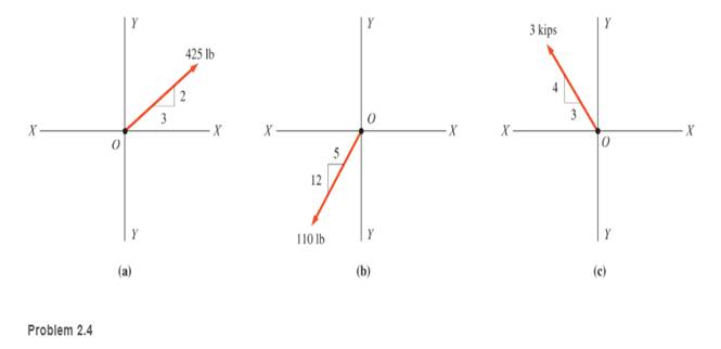
Chapter 2, Problem 2.4P
Compute the vertical and horizontal components for each of the forces shown.
Expert Solution & Answer

Learn your wayIncludes step-by-step video

schedule07:29
Students have asked these similar questions
The resistance R and load effect S for a given failure mode are statistically independent random variables
with marginal PDF's
FR (r) =
0≤r≤100
100'
fs(s)=0.05e0.05, 0
Qu 1 If crank OA rotates with an angular velocity of ω = 12 rad/s, determine the velocity of piston B and
the angular velocity of rod AB at the instant shown.
please show all work
Q2/ Maria has an online shop where she sells hand made paintings and
cards. She sells the painting for 50 and the card for 20. It takes her 2 hours
to complete 1 painting and 45 minutes to make a single card. She also has
a day job and makes paintings and cards in her free time. She cannot spend
more than 15 hours a week to make paintings and cards. Additionally, she
should make not more than 10 paintings and cards per week.
She makes a profit of 25 on painting and 15 on each card. How many
paintings and cards should she make each week to maximize her profit.
Chapter 2 Solutions
Applied Statics and Strength of Materials (6th Edition)
Ch. 2 - Find the resultant force for each system of forces...Ch. 2 - Rework Problem 2.1 solving for the resultants...Ch. 2 - Compute the vertical and horizontal components for...Ch. 2 - Compute the vertical and horizontal components for...Ch. 2 - Compute the vertical and horizontal components for...Ch. 2 - The rectangular components of a force are...Ch. 2 - Find the resultant force on the screw eye. One...Ch. 2 - Write a program that will calculate the...Ch. 2 - Write a program that will calculate me magnitude...Ch. 2 - Calculate and display the vertical and horizontal...
Ch. 2 - A plastic barrel containing water is used as an...Ch. 2 - A telephone pole is braced by a guy wire that...Ch. 2 - Compute the vertical and horizontal components for...Ch. 2 - Compute the vertical and horizontal components of...Ch. 2 - Compute the rectangular components parallel and...Ch. 2 - Determine the vertical and horizontal components...Ch. 2 - Find the vertical and horizontal components of...Ch. 2 - An inclined cable is used to pull on a log as...Ch. 2 - In Problem 2.18 , if the log will slide when a...Ch. 2 - A rope is bed to the top of a 10-m flagpole The...Ch. 2 - A rope tow is used to pull skiers up a...Ch. 2 - Determine the slope triangle dimension s so that...Ch. 2 - The crane wheel applies a 9500-lb forte to the...Ch. 2 - The horizontal and vertical components,...Ch. 2 - Calculate the X and Y components of each force...Ch. 2 - Find the resultant of the two force acting on the...Ch. 2 - A drawbar support assembly is shown in the figure....Ch. 2 - The Howe roof truss shown is subjected to wind...Ch. 2 - The release cam mechanism is subjected to the...
Additional Engineering Textbook Solutions
Find more solutions based on key concepts
Explain how each of the following types of integrity constraints is enforced in the SQL CREATE TABLE commands: ...
Modern Database Management
Is the instruction If 0 equals 0, then jump to Step 7 a conditional or unconditional jump? Explain your answer.
Computer Science: An Overview (13th Edition) (What's New in Computer Science)
Explain the term foreign key, and give an example.
Database Concepts (8th Edition)
17–1C A high-speed aircraft is cruising in still air. How does the temperature of air at the nose of the aircra...
Thermodynamics: An Engineering Approach
Write a program to answer questions like the following: Suppose the species Klingon ox has a population of 100 ...
Java: An Introduction to Problem Solving and Programming (8th Edition)
Comprehension Check 8-8
The temperature of dry ice is −109.3 degrees Fahrenheit [°F]. Convert this temperature ...
Thinking Like an Engineer: An Active Learning Approach (4th Edition)
Knowledge Booster


Learn more about
Need a deep-dive on the concept behind this application? Look no further. Learn more about this topic, mechanical-engineering and related others by exploring similar questions and additional content below.Similar questions
- For the beam and loading shown, (a) draw the shear and bending moment diagrams, (b) determine the magnitude and location of the maximum absolute value of the bending momentConsider A = 0please show step by step process, i did something wrong with bending moment diagram( length of beam = 2 + 6 + 2)arrow_forwardCORRECT ANSWER ONLY WITH COMPLETE FBD. PREFERABLY HANDWRITTEN. I WILL UPVOTE 1. The beam shown carries the following loads:Total dead load, wDL = 36 kN/mConcentrated live load, PLL = 240 kNThe beam section is HSS16X12X3/8 with properties:Span, L = 6 mArea, A = 12,100 mm2Moment of inertia about x-axis, Ix = 292 x 106 mm4Fy = 345 MPa 1. Calculate the location of the live load, from the left support, for maximum moment to occur at the fixed support.Answer: 2.536 m2. Calculate the maximum moment. Answer: 439.128 kN-marrow_forwardCORRECT ANSWER AND COMPLETE FBD ONLY. I PREFER HANDWRITTEN BUT ITS OKAY IF NOT. I WILL UPVOTE 2. The space truss shown is supported by ball-and-socket joints at A, B and C. Factored loads P1 and P2 areacting on joints D and E, respectively, towards the negative y-direction. 1. Calculate the stress of member CE, indicate tension or compression. Answer: 23.61 MPa Tension2. Calculate the stress of member AD, indicate tension or compression. Answer: 21.01 MPa Compression3. Calculate the stress of member CD, indicate tension or compression. Answer: 11.03 MPa Tensionarrow_forward
- CORRECT ANSWER AND COMPLETE FBD ONLY. I PREFER HANDWRITTEN BUT ITS OKAY IF NOT. I WILL UPVOTE 3. The frame has pin supports at A and E, subject to a wind load. Treat joint C to be an internal hinge. Given:Dimensions, H1 = 3.0 m; H2 = 4.5 m; L = 10.0 mWind loads, wWL (AB) = 4.8 kN/m; wWL (BC) = 3.9 kN/m; wWL (CD) = 1.5 kN/m; wWL (DE) = 1.2 kN/mMembers are made of A36 steel Wide Flange Section with the following properties:Area, A = 64000 mm2Depth, d = 762 mmFlange width, bf = 371 mmThickness of web, tw = 32 mmThickness of flange, tf = 57.9 mmMoment of inertia about x-axis, Ix = 6080 x 106 mm4The wide flange is oriented so that the bending is about the x-axis1. Calculate the stress in member AB, due to the axial load it carries, indicate if tension or compression.Answer: 0.0476 MPa Tension2. Calculate the stress in member DE, due to the axial load it carries, indicate if tension or compression.Answer: 0.2351 MPa Compression3. Calculate the maximum bending stress at B. Answer: 4.282 MPaarrow_forward32 mm 32 mm b' c' C 32 mm 32 mm b PROBLEM 6.41 a The extruded beam shown has a uniform wall thickness of 3 mm. Knowing that the vertical shear in the beam is 9 kN, determine the shearing stress at each of the five points indicated.arrow_forwardIn a structural reliability problem, the resistance (capacity) R and load effect (demand) S random variables associated with a failure mode of the structure of interest are normally distributed and statistically independent with the following probability distribution parameters (or statistics) in consistent units: MR = 12, σR = 3 μs = 5, σs = 2 (a) Determine the exact probability of failure pF ·arrow_forward
- The resistance R and load effect S for a given failure mode are statistically independent random variables with marginal PDF's 1 fR (r) = 0≤r≤100 100' fs(s)=0.05e-0.05s (a) Determine the probability of failure by computing the probability content of the failure domain defined as {rarrow_forwardPlease solve this problem as soon as possible My ID# 016948724arrow_forwardThe gears shown in the figure have a diametral pitch of 2 teeth per inch and a 20° pressure angle. The pinion rotates at 1800 rev/min clockwise and transmits 200 hp through the idler pair to gear 5 on shaft c. What forces do gears 3 and 4 transmit to the idler shaft? TS I y 18T 32T This a 12 x 18T C 48T 5arrow_forwardQuestion 1. Draw 3 teeth for the following pinion and gear respectively. The teeth should be drawn near the pressure line so that the teeth from the pinion should mesh those of the gear. Drawing scale (1:1). Either a precise hand drawing or CAD drawing is acceptable. Draw all the trajectories of the involute lines and the circles. Specification: 18tooth pinion and 30tooth gear. Diameter pitch=P=6 teeth /inch. Pressure angle:20°, 1/P for addendum (a) and 1.25/P for dedendum (b). For fillet, c=b-a.arrow_forward5. The figure shows a gear train. There is no friction at the bearings except for the gear tooth forces. The material of the milled gears is steel having a Brinell hardness of 170. The input shaft speed (n2) is 800 rpm. The face width and the contact angle for all gears are 1 in and 20° respectively. In this gear set, the endurance limit (Se) is 15 kpsi and nd (design factor) is 2. (a) Find the revolution speed of gear 5. (b) Determine whether each gear satisfies the design factor of 2.0 for bending fatigue. (c) Determine whether each gear satisfies the design factor of 2.0 for surface fatigue (contact stress). (d) According to the computation results of the questions (b) and (c), explain the possible failure mechanisms for each gear. N4=28 800rpm N₁=43 N5=34 N₂=14 P(diameteral pitch)=8 for all gears Coupled to 2.5hp motorarrow_forward1. The rotating steel shaft is simply supported by bearings at points of B and C, and is driven by a spur gear at D, which has a 6-in pitch diameter. The force F from the drive gear acts at a pressure angle of 20°. The shaft transmits a torque to point A of TA =3000 lbĘ in. The shaft is machined from steel with Sy=60kpsi and Sut=80 kpsi. (1) Draw a shear force diagram and a bending moment diagram by F. According to your analysis, where is the point of interest to evaluate the safety factor among A, B, C, and D? Describe the reason. (Hint: To find F, the torque Tд is generated by the tangential force of F (i.e. Ftangential-Fcos20°) When n=2.5, K=1.8, and K₁ =1.3, determine the diameter of the shaft based on (2) static analysis using DE theory (note that fatigue stress concentration factors need to be used for this question because the loading condition is fatigue) and (3) a fatigue analysis using modified Goodman. Note) A standard diameter is not required for the questions. 10 in Darrow_forwardarrow_back_iosSEE MORE QUESTIONSarrow_forward_ios
Recommended textbooks for you
 International Edition---engineering Mechanics: St...Mechanical EngineeringISBN:9781305501607Author:Andrew Pytel And Jaan KiusalaasPublisher:CENGAGE L
International Edition---engineering Mechanics: St...
Mechanical Engineering
ISBN:9781305501607
Author:Andrew Pytel And Jaan Kiusalaas
Publisher:CENGAGE L
Engineering Basics - Statics & Forces in Equilibrium; Author: Solid Solutions - Professional Design Solutions;https://www.youtube.com/watch?v=dQBvQ2hJZFg;License: Standard YouTube License, CC-BY