
Concept explainers
Videos
- The numbers of orbiting electrons in aluminum and silver are 13 and 47, respectively. Draw the electronic configuration for each, and discuss briefly why each is a good conductor.
- Using the Internet, find the atomic structure of gold and explain why it is an excellent conductor of electricity.
(a)
To draw:
The electronic configuration of aluminum and silver. Also, state the reason due to which both aluminum and copper are considered a good conductor.
Explanation of Solution
Given:
The numbers of orbiting electrons in aluminum and silver are
The arrangement of electron inside the atom and outside the nucleus follows a particular pattern. There is a shell structure in which all electron falls and the energy of the electrons decide which shell to fall. The number of electrons in each shell is always
In shell
In Shell
Inside shell, actually electron falls in sub-shell. The name of sub-shell are
In a nutshell, the larger the value of
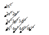
The electronic configuration of any element is based on below pattern:
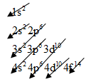
For aluminum, we know that the numbers of orbital electrons are 13.
So, arrange the electrons will be as below
The electronic configuration of Aluminum is
Here we can see, Aluminum has one free electron in its valence shell. Therefore, this free electron can move easily and hence, this causes the higher conductivity for Aluminum.
For silver, we know that the numbers of orbital electrons are 47.
So, arrange the electrons will be as follows:
The electronic configuration of silver is
Silver is a good conductor because it has free electrons in its valence shell. It is clearly seen from the electronic configuration of silver (
(b)
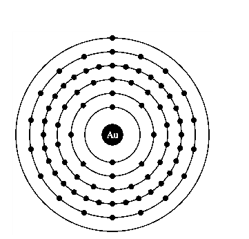
The atomic structure of the gold. Also, state the reason due is an excellent conductor of electricity.
Explanation of Solution
Atomic structure of gold.
The electronic configuration of any element is based on below pattern:
For gold, we know that the numbers of orbital electrons are
So, arrange the electrons for gold will be as follows:
The electronic configuration of gold is
Gold is a good conductor of electricity because it has free electrons in its valence shell.
It is clearly seen from the electronic configuration of gold that, s orbit is holding only one electron and maximum limit is up to
Want to see more full solutions like this?
Chapter 2 Solutions
Laboratory Manual for Introductory Circuit Analysis
Additional Engineering Textbook Solutions
Starting Out With Visual Basic (8th Edition)
Thinking Like an Engineer: An Active Learning Approach (4th Edition)
Java: An Introduction to Problem Solving and Programming (8th Edition)
Degarmo's Materials And Processes In Manufacturing
Web Development and Design Foundations with HTML5 (8th Edition)
Concepts Of Programming Languages


- A Three-phase, 12 pole, Y-connected alternator has 108 slots and 14 conductors per slot. The windings are (5/6 th) pitched. The flux per pole is 57 mWb distributed sinusoidally over the pole. If the machine runs at 500 r.p.m., determine the following: (a) The frequency of the generated e.m.f., (b) The distribution factor, (c) The pitch factor, and (d) The phase and line values of the generated e.m.f.?arrow_forwardTwo 3-ph, 6.6 kV, Y-connected, alternators supply a load of 3000 kW at 0.8 p.f. lagging. The synchronou impedance per phase of machine A is (0.5+110) and that of machine B is (0.4 +J12) . The excitation of machine A adjusted so that it delivers 150 A. The load is shared equally between the machines. Determine the armature curre p.f., induced e.m.f., and load angle of each machine?arrow_forwardName the circuit below? The output voltage is initially zero and the pulse width is 200 μs. Find the Vout and draw the output waveform? +2.5 V V 247 -2.5 V C 0.01 F Ri W 10 ΚΩarrow_forward
- Please work outarrow_forwardFind Vfinal when Vs up and Vs V. Which LED will light in each case? Red or Green? Justify your answers. Fill the table below. Vs 8 ΚΩ Vos Χρι + 3 ΚΩ www 6 ΚΩ ww 4 ΚΩ Yo www Vo Vec-12 V Nol V final Vm w 3 ΚΩ 5 V 38 ΚΩ R= 1 kQ V -12 V Red LED Green LED Vs Vo Vfinal Which LED is ON? Varrow_forwardCircuits help please solve and explain. Question in images providedarrow_forward
- + V 6.2 A 1.2 A S R 4 Ω Find the source voltage Vs 0.8 Aarrow_forwardDetermine i(t) for t≥ 0 given that the circuit below had been in steady state for a long time prior to t = 0. Also, I₁ = 1 5 A, R₁ =22, R2 =10 Q2, R3 = 32, R4 =7 2, and L=0.15 H. Also fill the table. m L ww R2 t = 0 R₁ 29 R3 R4 Time 0 iL(t) 0 8arrow_forwardPlease help explain this problemarrow_forward
- + P = 16 W w w P = 8 W I R₁ R2 E = RT=322 1- Determine R1, R2, E ΙΩarrow_forward+ 30 V = - 20 V + R 2- Use KVL to find the voltage V - V + + 8 Varrow_forwardFind the Thévenin equivalent circuit for the portions of the networks in Figure external to the elements between points a and b. a R₁ 2002 I = 0.1 A 0° Xc : 32 Ω R2 = 6802 20 Ω фъarrow_forward
 Electricity for Refrigeration, Heating, and Air C...Mechanical EngineeringISBN:9781337399128Author:Russell E. SmithPublisher:Cengage Learning
 Delmar's Standard Textbook Of ElectricityElectrical EngineeringISBN:9781337900348Author:Stephen L. HermanPublisher:Cengage Learning