
Concept explainers
Videos
The resultant force the water and surrounding air exert on the cap at B.
Explanation of Solution
Given:
Absolute pressure at point A
Inner diameter of the pipe
Atmospheric pressure
Pressure head of water
Density of water
Acceleration due to gravity is
Calculation:
Draw the free body diagram of the pipe as in Figure (1).
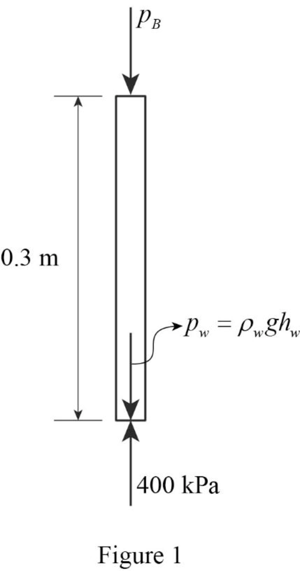
Determine the pressure at point B
Draw the pressure distribution on the pipe as in Figure (2).
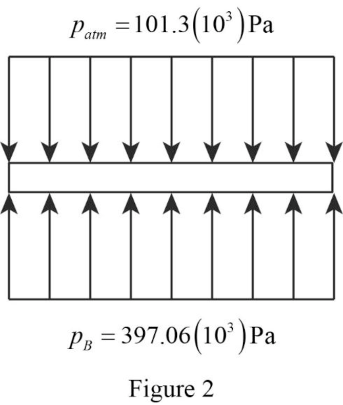
Determine the area of the pipe (A).
Determine the resultant force
Thus, the resultant force the water and surrounding air exert on the cap at B is
Want to see more full solutions like this?
Chapter 2 Solutions
EBK FLUID MECHANICS


- 7) find the Emax for figure below. 250N Ans: Tmay 7.5 MPa Gomm 350mm 50mm 4arrow_forwardWater is supplied at 150 ft³/s and 70 psi to a hydraulic turbine through a 3-ft inside-diameter inlet pipe as indicated in the figure below. The turbine discharge pipe has a 4.8-ft inside diameter. The static pressure at section (2), 10 ft below the turbine inlet, is 10 in. Hg vacuum. If the turbine develops 2400 hp, determine the rate of loss of available energy between sections (1) and (2). Section (1) P₁ =70psi Q=150ft³/s D₁ = 3 ft 10 ft Turbine power loss = i P₂ = 10 in. Hg vacuum D₂ =4.8ft Section (2) de hparrow_forwardThis problem studies the response of two single degree of freedom bridge systems shown in Figure 1 under three loading cases. The problem has two parts. Part A and Part B use the same loading cases but the system is modified. Assume the following three loading cases in both Part A and Part B: (a) Harmonic wind load acting on the bridge deck pw(t) = powsin(ωwt) with amplitude pow and forcing circular frequency ωw. (b) Harmonic displacement base excitation acting at the base of the bridge pier ug(t) = ugosin(ωgt) with amplitude ugo and displacement circular frequency ωg. (c) Rectangular pulse load acting on the bridge deck with amplitude pop and pulse duration td. Part A The system includes part of a bridge deck and a bridge pier shown in Figure 1(a). For each loading case find the symbolic expression of the peak shear force in the bridge pier assuming the following: • The bridge deck is rigid and it has a mass m. • The bridge deck is rigidly connected with the bridge pier (i.e.,…arrow_forward
- specific speed P #2 Q.2. A Pelton wheel turbine of 1.9 m diameter works under a head of 50 m at 150 rpm. The buckets are exposed to water jet which delivers from a nozzle of 20 cm in diameter. Find the overall efficiency power produced by the wheel if the buckets deflects the jet through an angle of 163°. coefficient of velocity as 0.98 [50 Marks] ·licosply Y and no Take thearrow_forwardd Q.2. A Pelton wheel has a mean bucket speed of 15 m/s. The jet of water issued from a nozzle of 12 cm in diameter impinges the bucket with a velocity of 40 m/s. If the buckets deflect the jet through an angle of 165°, find the head and power generated by the turbine. Assume the hydraulic efficiency is 90% and the mechanical efficiency is 85%. [50 Marks] Po 7n = 90%arrow_forwardAt its optimum point of caines. operation, a given centrifugal pump with an impeller diameter of 50 cm delivers 3.2 m³/s of water at a 2 head of 25 m when rotating at 1450 rpm and power of 955 kW. If a homologous pump with an impeller diameter of 80 cm rotates at 1200 rpm, what would be the discharge, head, shaft break power and P H₂arrow_forward
- (read image)arrow_forwardHi, can you please assist with the attached question please. Please do not use Ai software. Many thanks.arrow_forwarddetermine the allowable bending and contact stresses for a grade 1 steel through-hardened to 250 HB. Assume the desired reliability is 50% and that the pinion and gear have the same hardness and the gear encounters hydrodynamic lubrication and is to last ten million cyclesarrow_forward
- Using the four-point bending tool, detail the influence of both applied load and notch size on the transverse strain. Cover the following points in your answer. a. A detailed description of the methodology you have used to create a set of results suitable to answer this question. Include details on the placement of line scans, the loads used, etc. (there is no need to describe the process of extracting the data from the interactive or the fundamental principles behind DIC). (5 marks) b. A description of the results you have found, including a written description, images, and both vertical and horizontal line scans from the four-point bending tool. Include a minimum of three loads and three notch sizes in your results. (20 marks) c. The conclusions you can make regarding the influence of load and notch size on the strain experienced by the beam based on the data you collect. (5 marks) To achieve full marks, you will need to include the following in your work: • properly labelled graphs…arrow_forwardUsing the four-point bending tool, discuss how measurements of transverse strain using DIC and compare with those from the strain gauge attached at the centre top of the specimen. In your answer, include the following: a. A short explanation of how each of the strain measurement techniques works. (4 marks) b. A description of the methodology you have used to make the data that you discussed from each technique as comparable as possible. (6 marks) c. A set of figures (images, graphs and/or tables as necessary) with appropriate captions demonstrating the comparability of data extracted from the two strain measurement methods. This should include at least three different applied loads. (10 marks) d. A brief description of the findings. (5 marks)arrow_forwardAn undamped single-degree-of-freedom system consists of a spring with stiffness k = 10 kip/in and a mass weighing W = 10 kips. The system is at rest and it is suddenly subjected to a half-cycle sine pulse force. The pulse force has an amplitude po = 1 kips and time duration td = 0.1 seconds. Calculate the maximum restoring force in the spring due to the pulse force.arrow_forward
 Elements Of ElectromagneticsMechanical EngineeringISBN:9780190698614Author:Sadiku, Matthew N. O.Publisher:Oxford University Press
 Mechanics of Materials (10th Edition)Mechanical EngineeringISBN:9780134319650Author:Russell C. HibbelerPublisher:PEARSON
 Thermodynamics: An Engineering ApproachMechanical EngineeringISBN:9781259822674Author:Yunus A. Cengel Dr., Michael A. BolesPublisher:McGraw-Hill Education
 Control Systems EngineeringMechanical EngineeringISBN:9781118170519Author:Norman S. NisePublisher:WILEY
 Mechanics of Materials (MindTap Course List)Mechanical EngineeringISBN:9781337093347Author:Barry J. Goodno, James M. GerePublisher:Cengage Learning
 Engineering Mechanics: StaticsMechanical EngineeringISBN:9781118807330Author:James L. Meriam, L. G. Kraige, J. N. BoltonPublisher:WILEY