Principles Of Foundation Engineering 9e
9th Edition
ISBN: 9781337705035
Author: Das, Braja M.
Publisher: Cengage,
expand_more
expand_more
format_list_bulleted
Concept explainers
Textbook Question
Chapter 19, Problem 19.3P
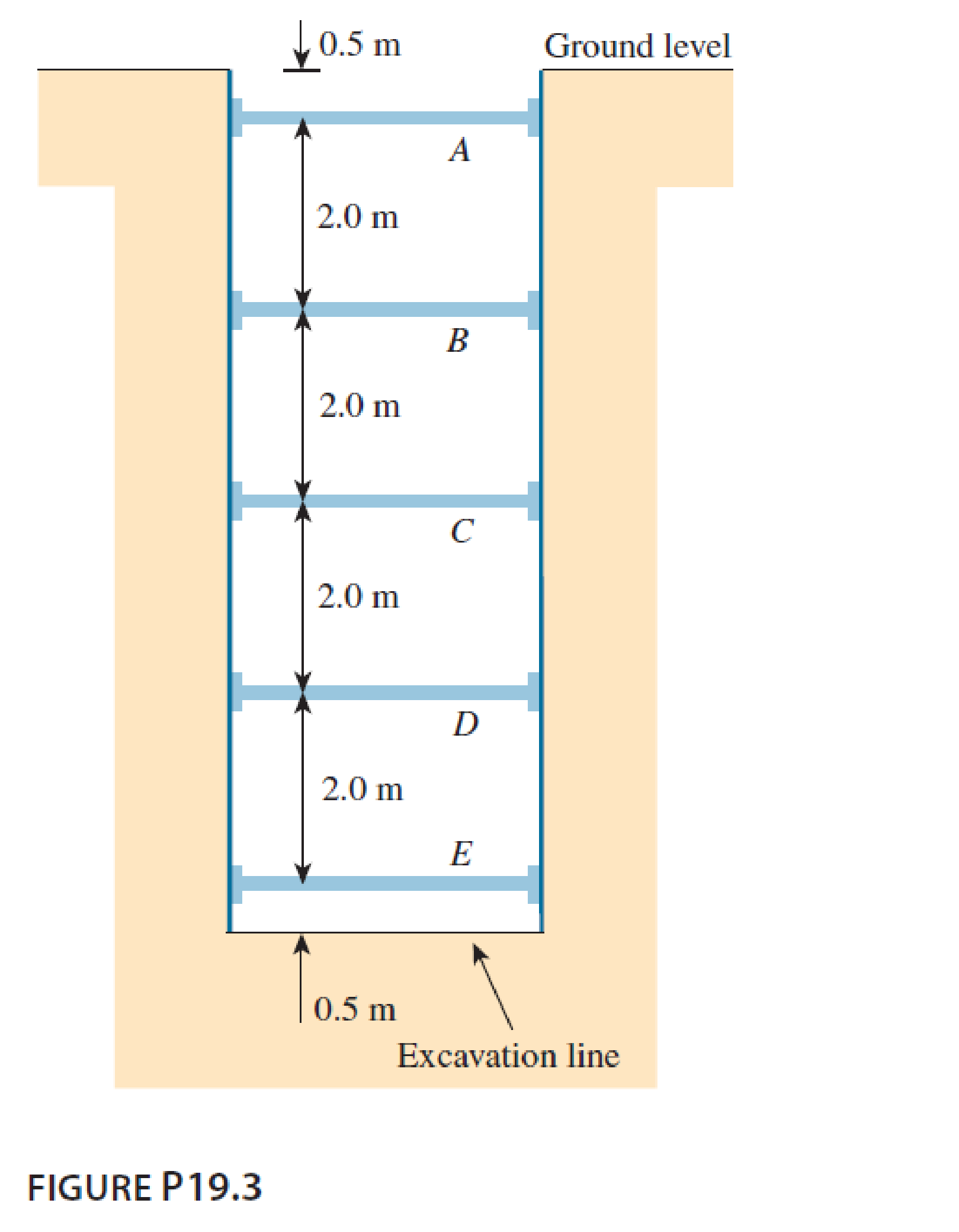
A braced cut shown in Figure P19.3 is to be made to a depth of 9.0 m in a saturated clay deposit where the unit weight is 17.65 kN/m3 and the undrained shear strength is 30 kN/m2. The struts are spaced horizontally at 3.0 m center to center. Find the strut loads.

Expert Solution & Answer
Trending nowThis is a popular solution!

Students have asked these similar questions
In order to solve the frame given below with the Force Method, remove restraints from
joints A and G and draw only the bending moment diagrams Mo, M₁, M2 and M3 for
this case. (25 Pts.)
Note: Only bending moment diagrams that are used for the solution are required.
There is no need to do any further calculations.
4 kN
B
I
E
D
2 kN/m
H
3 m
3 m
4 m
+
2 m
4m
please show complete solution with formula
please show complete solution, thank you
Chapter 19 Solutions
Principles Of Foundation Engineering 9e
Knowledge Booster
Learn more about
Need a deep-dive on the concept behind this application? Look no further. Learn more about this topic, civil-engineering and related others by exploring similar questions and additional content below.Similar questions
- please show complete solution, step by step, thanksarrow_forward1. What is the weight of each block shown below in pounds? A) 2’x2’x10’ Steel Bar w=490lb/ft^3 B) 5’x4’x3’ Concrete Block w=150lb/ft^3 A) 3’x10’x2’ Wood block w=50lb/ft^3 2.The 6” thick, 20’x25’ concrete slab weights 150lbs/ft^3 and has an area load of 50lbs/ft^2 (psf). What is the total load of the floor?arrow_forwardLab Assignment #2 Loads: UDL and Concentrated Name: TA 1. Use the provided beam models to solve for the equivalent concentrated load of each beam configuration. Draw the loading conditions showing the equivalent concentrated load(s). a) w = 30lbs/ft 6ft 6ft c) w = 50lbs/ft 12ft w = 70lbs/ft b) 4ft w = 20lbs/ft w = 40lbs/ft d) 9ft 2. Find the equivalent concentrated load(s) for the bags of cement stacked on the dock as shown here. Each bag weighs 100 lbs and is 12 inches long. Draw the loading conditions for each showing the equivalent concentrated load(s). 1 bag = 100lbs L= 12 ft L= 6ft L= 8ftarrow_forward
- please show the complete solution, step by step process, thanksarrow_forwardThe rectangular gate shown in figure rotates about an axis through N. If a=3.3 ft,b=1.3 ft, d=2 ft, and the width perpendicular to the plane of the figure is 3 ft, what torque(applied to the shaft through N) is required to hold the gate closed?arrow_forwardAn elevated tank feeds a simple pipe system as shown. There is a fire hydrant atpoint C. The minimum allowable pressure at point C is 22 psig for firefighting requirements.What are the maximum static head (in ft) as well as pressure (in psig) at point C (i.e. nodischarge in the system)? Do we meet the pressure requirement for firefighting? (Please donot worry about L or d in the figure below)arrow_forward
- 12. For the beam loaded and supported as shown, determine the following using Point Load Analogous via Integration: a. the rotation at the left support. b. the deflection at midspan R1 1 . m 600 N/m 3 m + 2 m R2arrow_forward14. Find the reaction R and the moment at the wall for the propped beam shown below using Point Load Analogous via Integration: 16 kN/m 000 4.5m 4.5marrow_forward13. Determine the moment at supports A and B of the fixed ended beam loaded as shown using Point Load Analogous via Integration: 10 kN/m 9 kN/m 3 m 3 m 12 kN/marrow_forward
- How does construction estimate inaccuracies lead to delays and complications that impact projects?arrow_forwardQ5: Given the following system: น -3 y= [4 -2] +3u Generate a model with states that are the sum and difference of the original states.arrow_forward4. Draw a stress-strain curve (in tension and compression) for a reinforced concrete beam below. Label the important parts of the plot. Find the linear elastic approximation obtained using the transformed technique, and plot over the same strain ranges. 24" 4" 20" 16" f = 8,000 psi 8- #11 bars Grade 60 steel 4" (f, = 60 ksi and E₁ = 29000 ksi)arrow_forward
arrow_back_ios
SEE MORE QUESTIONS
arrow_forward_ios
Recommended textbooks for you
 Principles of Foundation Engineering (MindTap Cou...Civil EngineeringISBN:9781337705028Author:Braja M. Das, Nagaratnam SivakuganPublisher:Cengage Learning
 Principles of Geotechnical Engineering (MindTap C...Civil EngineeringISBN:9781305970939Author:Braja M. Das, Khaled SobhanPublisher:Cengage Learning
 Fundamentals of Geotechnical Engineering (MindTap...Civil EngineeringISBN:9781305635180Author:Braja M. Das, Nagaratnam SivakuganPublisher:Cengage Learning
 Principles of Foundation Engineering (MindTap Cou...Civil EngineeringISBN:9781305081550Author:Braja M. DasPublisher:Cengage Learning

Principles of Foundation Engineering (MindTap Cou...
Civil Engineering
ISBN:9781337705028
Author:Braja M. Das, Nagaratnam Sivakugan
Publisher:Cengage Learning

Principles of Geotechnical Engineering (MindTap C...
Civil Engineering
ISBN:9781305970939
Author:Braja M. Das, Khaled Sobhan
Publisher:Cengage Learning

Fundamentals of Geotechnical Engineering (MindTap...
Civil Engineering
ISBN:9781305635180
Author:Braja M. Das, Nagaratnam Sivakugan
Publisher:Cengage Learning

Principles of Foundation Engineering (MindTap Cou...
Civil Engineering
ISBN:9781305081550
Author:Braja M. Das
Publisher:Cengage Learning
How to build angle braces; Author: Country Living With The Harnish's;https://www.youtube.com/watch?v=3cKselS6rxY;License: Standard Youtube License