
Concept explainers
Videos
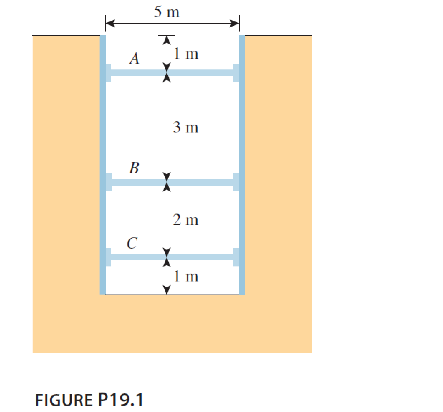
A 5 m wide braced excavation is made in a saturated clay, as shown in Figure P19.1, with the following properties: c = 20 kN/m2, ϕ = 0, and γ = 18.5 kN/m3. The struts are spaced at 5 m center to center in plan.
- a. Determine the strut forces.
- b. Determine the section modulus of the sheet pile required, assuming σall = 170 MN/m2.
- c. Determine the maximum moment for the wales at levels B and C.
a.
Find the strut force.
Answer to Problem 19.1P
The strut load at A, B, C is
Explanation of Solution
Given information:
The width of excavation is 5 m.
The height of excavation cut H is 7 m.
The unit weight of saturated clay
The coefficient of internal friction
The cohesion (c) is
The center to center spacing of strut s is 5 m.
Calculation:
Check the condition for soft to medium clay as follows:
Hence, the clay is considered as soft to medium clay.
Find the maximum lateral pressure using the formula.
The maximum lateral pressure is
Step-1:
Indicate the struts are labeled as A, B, and C and its carrying load as
Draw the pressure diagram as shown in Figure.
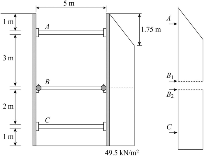
The strut sheet pile connection at B is assumed to be hinge.
Find the strut load per meter width of excavation as follows:
At the top block,
For the bottom block,
Find the strut force at A
Find the strut load at B
Find the strut load at C
Therefore, The strut load at A, B, C is
b.
Find the required section modulus for sheet pile section.
Answer to Problem 19.1P
The section modulus is
Explanation of Solution
Given information:
The allowable pressure
Calculation:
For top block,
Consider the maximum moment occurs at distance
Find the maximum moment as follows:
The maximum moment occurs at C in the lower block
Find the maximum moment at lower block as follows:
Consider that the higher value of maximum moment is
Find the required section modulus using the formula:
Refer Table 18.1, “Properties of some commercially available sheet-pile section” in the textbook.
Take the section designation as PZ-22 according to the values.
Therefore, the section modulus is
c.
Find the maximum moment for the two wales.
Answer to Problem 19.1P
The maximum moment for the wall at B is
The maximum moment for the wall at C is
Explanation of Solution
Find the maximum moment for the wall at B,
Find the maximum moment for the wall at C,
The maximum moment for the wall at B is
The maximum moment for the wall at C is
Want to see more full solutions like this?
Chapter 19 Solutions
Principles of Foundation Engineering (MindTap Course List)


- compute the load bearing capacity, displacement, stress distribution, tabulate the answersarrow_forwardcompute the load bearing capacity, displacement, and stress distribution, tabulate the answersarrow_forwardcompute the load bearing capacity, displacement, stress distribution, tabulate the answersarrow_forward
- By using the yield line theory, determine the ultimate resisting moment per linear meter (m) for an isotropic reinforced concrete two-way slab to sustain a concentrated factored load of P kN applied as shown in figure. Use equilibrium method in solution Column 2.0 P 8.0 m m m XXXXarrow_forwardBy using the yield line theory, determine the ultimate resisting moment (m) for an isotropic reinforced concrete two-way slab shown in figure under a uniform load (q). Use equilibrium method in solution m m column 20 m 20 marrow_forwardIn Tikrit city, environmental engineers are monitoring the diffusion of CO2 in the air as part of a pollution control study. The air-carbon dioxide mixture is at 295 K and 202.6 kPa, and the concentration of CO2 at two planes, 3 mm apart, is 25 vol.% at the first plane and 15 vol.% at the second plane. The diffusivity of CO2 in air under these conditions is 8.2 × 10⁶ m²/s. The study aims to calculate the rate of CO2 transfer across these two planes in two different scenarios: 1. What is the main engineering issue being addressed in this scenario? 2. Calculate the concentration of CO2 at the two planes in mol/m³ and determine the rate of transfer of CO2 using the diffusivity of CO2 in air. 3. With an engineering solution approach to solve the issue, calculate the rate of transfer of CO2 across the two planes assuming two scenarios: equimolecular counter diffusion and diffusion through a stagnant air layer. 4. Determine if there is a significant difference between the results of…arrow_forward
- Introduction: Orifice and Free Flow Jet in Applied Fluid Mechanics' I need to introduction only for answerarrow_forwardThe circular slab of radius 2 m supported by three columns, as shown in figure, is to be isotropically reinforced. Find the ultimate resisting moment per linear meter (m) required just to sustain a uniformly distributed load (q) equals 16 kN/m². Use equilibrium method in solution m Column marrow_forwardVehicles begin to arrive at a parking lot at 7:45 A.M. at a constant rate of 4 veh/min and continue to arrive at that rate throughout the day. The parking lot opens at 8:00 A.M. and vehicles are processed at a constant rate of one vehicle every 10 seconds. Assuming D/D/1 queuing, what is the longest queue, the queue at 8:15 A.M., and the average delay per vehicle from 7:45 A.M. until the queue clears?arrow_forward
- 1. Gunakan teor luasi momen untuk menentukan putaran sudut (slope) di B. Gunakan E = 200 GPa dan I-70 x 100 mm². m 8 kN·m B 2. Gunakan teori luas momen dan tentukan putaran sudut (slope) di A dan perpindahan di C. Gunakan E = 200 GPa dan I = 70 x 100 mm². 4 kN 4 kN -2 m 2 m- B 4 m 4 marrow_forwardConsider the conditions in Practice Problem 5.2. How short would the driver reaction times of oncoming vehicles have to be for the probability of an accident to equal 0.20?arrow_forwardPart 4: Problem-Solving. Solve the following problems. Show all calculations. 1. A Standard Penetration Test (SPT) was conducted at a site, and the following blow counts were recorded: Depth: 2 m, Blow count (N): 10 D D Depth: 4 m, Blow count (N): 15 Depth: 6 m, Blow count (N): 20 The energy ratio is 60%, and the overburden correction factor CN is 1.1. Calculate the corrected N-values for each depth. 2. A soil sample was collected from a depth of 3 m using a Shelby tube. The sample had a volume of 0.01 m³ and a mass of 18 kg. If the water content is 12%, calculate the (a) bulk density, (b) dry density, and (c) void ratio of the soil. Assume the specific gravity of soil solids (Gs) is 2.65. 3. A Cone Penetration Test (CPT) was conducted at a site, and the following data was obtained: Depth: 2 m, Cone resistance (qc): 5 MPa Depth: 4 m, Cone resistance (qc): 8 MPa Depth: 6 m, Cone resistance (qc): 12 MPa Estimate the soil type at each depth using typical qc correlations.arrow_forward
 Principles of Foundation Engineering (MindTap Cou...Civil EngineeringISBN:9781337705028Author:Braja M. Das, Nagaratnam SivakuganPublisher:Cengage Learning
 Principles of Foundation Engineering (MindTap Cou...Civil EngineeringISBN:9781305081550Author:Braja M. DasPublisher:Cengage Learning
 Principles of Geotechnical Engineering (MindTap C...Civil EngineeringISBN:9781305970939Author:Braja M. Das, Khaled SobhanPublisher:Cengage Learning
 Fundamentals of Geotechnical Engineering (MindTap...Civil EngineeringISBN:9781305635180Author:Braja M. Das, Nagaratnam SivakuganPublisher:Cengage Learning