Concept explainers
Videos
(a)
The couple
Answer to Problem 18.77P
The couple
Explanation of Solution
Given information:
The total mass is
Write the expression for the sum of the moment acting on the body along x -direction.
Here, the product of the moment of the inertia of
Write the expression for the sum of the moment acting on the body along y -direction.
Write the expression for the sum of the moment acting on the body along z -direction.
Here, the moment of the inertia along the z -direction is
Draw the diagram for the for the sheet metal component.
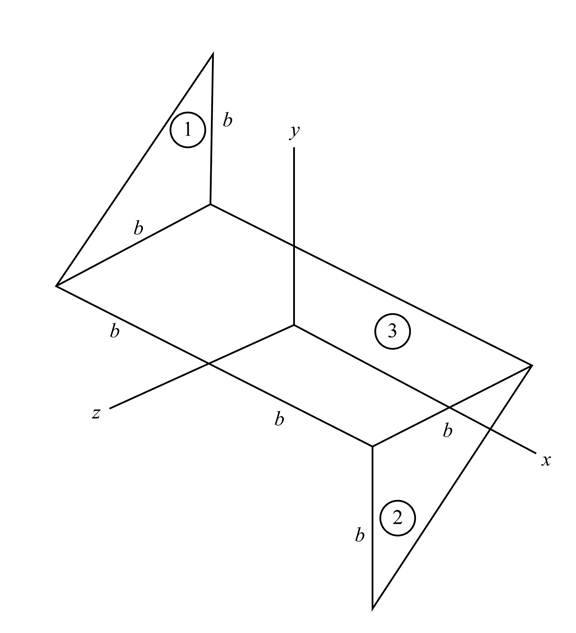
Figure-(1)
Write the expression for the area of the section 1 shown in the Figure-(1).
Here, the constant dimension is
Write the expression for the area of the section 2 shown in the Figure-(1).
Write the expression for the area of the section 3 shown in the Figure-(1).
Write the expression for the total area of the sheet.
Substitute
Write the expression of mass per unit area of the system.
Here, the mass of the sheet metal component is
Write the expression for the variation of the
Here, the coordinate of the considered point is
The below figure represent the schematic diagram of the elemental strip of section 1.
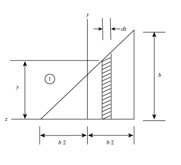
Figure-(2)
Write the expression for the distance of the centroid of the element from the
Write the expression for the mass of the elemental strip.
Here, the area of the elemental strip is
Write the expression for the moment of inertia of the element with respect to z- axis.
Write the expression for the moment of the inertia of the section 1.
Write the expression for the product of moment of inertia of the plane
Write the expression for the product of moment of inertia of the plane
Write the expression for the variation of the
The below figure represent the schematic diagram of the elemental strip of section 2.
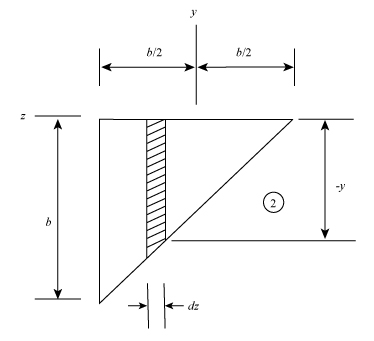
Figure-(3)
Write the expression for the mass of the elemental strip of section 2.
Write the expression for the moment of the inertia of the section 2.
Write the expression for the product of moment of inertia of the plane
Write the expression for the product of moment of inertia of the plane
Write the expression of mass per unit area of the section3 in Figure-(1).
Here, the mass of the rectangular sheet metal component is
Write the expression for the moment of the inertia of the section 3.
The product moment of the inertia for the plane
Write the expression for the moment of the inertia of the whole system.
Write the expression for the product of moment of inertia of the whole system.
Write the expression for the product of moment of inertia of the whole system.
Draw the diagram for the system to shows the action of forces on the system.
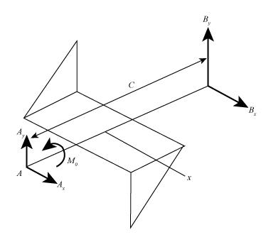
Figure-(4)
Here, the reaction on the point
Calculation:
Substitute
Substitute
Substitute
Substitute
Substitute
Substitute
Substitute
Substitute
Substitute
Conclusion:
The couple
(b)
The dynamic reactions at
The dynamic reactions at
Answer to Problem 18.77P
The dynamic reactions at
The dynamic reactions at
Explanation of Solution
Write the expression for the dynamic reaction at point
Write the expression for the dynamic reaction at point
Write the expression for the reaction forces along the y- direction.
Write the expression for the reaction forces along the x- direction.
Write the expression for the sum of the moment acting on the body along x -direction.
Here, distance between the point
Write the expression for the sum of the moment acting on the body along y -direction.
Calculation:
Substitute
Substitute
Substitute
Substitute
Substitute
Substitute
Substitute
Substitute
Substitute
Substitute
Substitute
Substitute
Substitute
Substitute
Conclusion:
The dynamic reactions at
The dynamic reactions at
Want to see more full solutions like this?
Chapter 18 Solutions
Vector Mechanics for Engineers: Dynamics


- Homework#5arrow_forwardQuestion 1: Beam Analysis Two beams (ABC and CD) are connected using a pin immediately to the left of Point C. The pin acts as a moment release, i.e. no moments are transferred through this pinned connection. Shear forces can be transferred through the pinned connection. Beam ABC has a pinned support at point A and a roller support at Point C. Beam CD has a roller support at Point D. A concentrated load, P, is applied to the mid span of beam CD, and acts at an angle as shown below. Two concentrated moments, MB and Mc act in the directions shown at Point B and Point C respectively. The magnitude of these moments is PL. Moment Release A B с ° MB = PL Mc= = PL -L/2- -L/2- → P D Figure 1: Two beam arrangement for question 1. To analyse this structure, you will: a) Construct the free body diagrams for the structure shown above. When constructing your FBD's you must make section cuts at point B and C. You can represent the structure as three separate beams. Following this, construct the…arrow_forwardA differential element on the bracket is subjected to plane strain that has the following components:, Ɛx = 300 × 10-6, Ɛy = 150 × 10-6, Ɛxy = -750 x 10-6. Use the strain-transformation equations and determine the normal strain Ɛx in the X/ direction on an element oriented at an angle of 0 = 40°. Note, a positive angle, 0, is counter clockwise. x Enter your answer in micro strain to a precision of two decimal places. eg. if your answer is 300.15X10⁶, please enter 300.15.arrow_forwardIf the 50 mm diameter shaft is made from brittle material having an ultimate strength of σult=595 MPa for both tension and compression, determine the factor of safety of the shaft against rupture. The applied force, F, is 140 kN. The applied torque T, is 5.0 kN⚫m. Enter your answer to a precision of two decimal places. T Farrow_forwardЗіс 1 mH 10 Ω m 16 cos 2.5 × 10⁴ A Lic 592 10 Ω 1 μFarrow_forwardHomework#5arrow_forwardHomework#5arrow_forwardOxygen (molar mass 32 kg/kmol) expands reversibly in a cylinder behind a piston at a constant pressure of 3 bar. The volume initially is 0.01 m3 and finally is 0.03 m3; the initial temperature is 17°C. Calculate the work input and the heat supplied during the expansion. Assume oxygen to be an ideal gas and take cp = 0.917 kJ/kg K. For 1 bonus mark explain why (using your understanding of thermodynamics) that oxygen is used in this context rather than water vapour.arrow_forwardHydrodynamic Lubrication Theory Q1: Convert this equations into Python by 1- ah ap a h³ ap 1..ah = ax 12μ ax ay 12μ ay 2 ax Where P=P(x, y) is the oil film pressure. 2- 3μU (L² ε sin P= C²R (1+ cos 0)³ Q2: prove that |h(0) = C(1+ cos 0) ?arrow_forward### To make a conclusion for a report of an experiment on rockets, in which the openrocket software was used for the construction and modeling of two rockets: one one-stage and one two-stage. First rocket (single-stage) reached a maximum vertical speed of 200 m/s and a maximum height of 1000 m The second rocket (two-stage) reached a maximum vertical speed of 250 m/s and a maximum height of 1800 m To make a simplified conclusion, taking into account the efficiency of the software in the study of rocketsarrow_forwardWhat is the difference between saturated liquid and compressed liquid? What is the difference between the critical point and the triple pointarrow_forwardWhat is quality? Does it have any meaning in the superheated vapour region? What is the difference between saturated vapor and superheated vapour? What is the difference between saturated liquid and compressed liquid? What is the difference between the critical point and the triple point?arrow_forwardarrow_back_iosSEE MORE QUESTIONSarrow_forward_ios
 Elements Of ElectromagneticsMechanical EngineeringISBN:9780190698614Author:Sadiku, Matthew N. O.Publisher:Oxford University Press
 Mechanics of Materials (10th Edition)Mechanical EngineeringISBN:9780134319650Author:Russell C. HibbelerPublisher:PEARSON
 Thermodynamics: An Engineering ApproachMechanical EngineeringISBN:9781259822674Author:Yunus A. Cengel Dr., Michael A. BolesPublisher:McGraw-Hill Education
 Control Systems EngineeringMechanical EngineeringISBN:9781118170519Author:Norman S. NisePublisher:WILEY
 Mechanics of Materials (MindTap Course List)Mechanical EngineeringISBN:9781337093347Author:Barry J. Goodno, James M. GerePublisher:Cengage Learning
 Engineering Mechanics: StaticsMechanical EngineeringISBN:9781118807330Author:James L. Meriam, L. G. Kraige, J. N. BoltonPublisher:WILEY