
Concept explainers
Videos
Estimate the air temperatures and corresponding speeds of sound at altitudes of
Answer to Problem 35P
The air temperatures and corresponding speeds of sound at altitudes of
Explanation of Solution
Given data:
Refer to Table given in problem 18.35 in textbook,
The air temperature at altitude
The air temperature at altitude
The speed of sound at altitude
The speed of sound at altitude
The air temperature at altitude
The air temperature at altitude
The speed of sound at altitude
The speed of sound at altitude
Formula used:
Formula for the linear interpolation is,
Calculation:
To find the air temperature at altitude
The diagrammatic representation for the given value is drawn below,
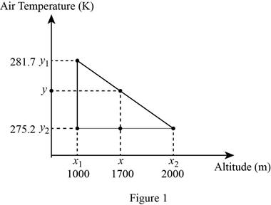
Substitute
Equation (2) can be reduced as follows,
Reduce the equation as follows,
Therefore, the air temperature at an altitude
To find the speed of sound at an altitude
The diagrammatic representation for the given value is drawn below,
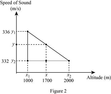
Substitute
Equation (3) can be reduced as follows,
Reduce the equation as,
Therefore, the approximate value of speed of sound at an altitude
To find the air temperature at altitude
The diagrammatic representation for the given value is drawn below,
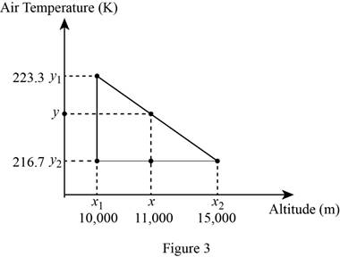
Substitute
Equation (4) can be reduced as follows
Reduce the equation as follows,
Therefore, the air temperature at an altitude
To find the speed of sound at an altitude
The diagrammatic representation for the given value is drawn below,
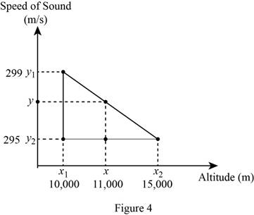
Substitute
Equation (5) can be reduced as follows
Reduce the equation as follows,
Therefore, the approximate value of speed of sound at an altitude
Conclusion:
Thus, the air temperatures and corresponding speeds of sound at altitudes of
Want to see more full solutions like this?
Chapter 18 Solutions
EBK ENGINEERING FUNDAMENTALS: AN INTROD


- I need Help some hw for AutoCAD please use measure front top and side viewarrow_forwardCalculate the discharge of the system shown below. Neglecting minor losessarrow_forwardQ3. Statically determinate or indeterminate beam analysis by the stiffness method a) Determine the global stiffness matrix of the beam shown in Fig. 3. Assume supports at 1 and 3 are rollers and the support at 2 is a pinned support. Indicate the degrees- of freedom in all the stiffness matrices. El is constant. Use the values of w = 50 kN/m and L1 = 2.0 m Note, L2-3L1. b) Determine the rotations at all the nodes of the beam and reactions at the supports. Show all calculations. c) Draw the BMD of the beam on the compression side showing the salient values. What are the maximum bending moments of the beam? Draw the deflected shape of the beam. d) Solve the problem using the Strand7. Assume any suitable value of El (state the value you have used for El). Show the model with all the nodes, element numbers and boundary conditions. Display the deflected shape and BMD. e) Show a table comparing the stiffness method (manual calculations) of the all the reactions and the maximum bending moment…arrow_forward
- Using AutoCAD. I need help please to exact measurearrow_forwardDraw Isometric view of this multiview of object.arrow_forwardREMINDER: The truss must be cut into two different sections. You can choose either one to solve as you will get the same answer. Since there are three equations available, you can't cut more than three members 6.25 Determine the force in members BD, CD, and CE of the truss shown. BO C 36 kips 36 kips D F H 7.5 ft E G 4 panels at 10 ft = 40 ftarrow_forward
- Calculate the area of the following polygon using the abscissa and projection method, taking into account the necessary adjustments before calculating the area of the polygon using the compass rule. Latitude Departure Side 930.63 N 930.63 S 1272 E 1271 W AB 122.14 E=12/2-1271-1 cr=-1 680 BC 173.83 length 591 CD 669.13 109.08 DE 139.36 961.1 EA 756.80 201.82 330.63/ 430.65 DEP=L SIN (O) >L DEP/SIN(O) LAT = L COS (0) DEPILATESIN(OYCOS (0)= TAN (0) O TAN-1 (DEP/LAT)= asztan Deptarrow_forwardEstimate the material quantities (cement, sand, gravel, and steel reinforcement) required for constructing 120 m concrete channel of the following typical cross section, concrete mix of 1:1.5:3 and thickness of 20 cm. Figure (1) Figure (1) 12250- 16300arrow_forwarda) A 14-ft. tall and12-ft.-8-in. long fully grouted reinforced masonry wall is constructed of 8-in.CMU. It is to be analyzed for out-of-plane loading. Construct thenP -nM curves for the wallwith the following three vertical reinforcement scenarios: (1) 10 No. 6 bars at 16 in. spacing,(2) 10 No. 5 bars at 16 in. spacing, and (3) 7 No. 4 bars at 24 in. spacing. The steel is Grade60 with a modulus of elasticity of 29,000 ksi, and the masonry has a compressive strength of2,000 psi. You may use Excel or Matlab to construct the curves. Also, show the maximumnPallowed by the code for each case.(b) For each of the above reinforcement scenarios, determine the maximum axial loads that arepermitted for the tension-controlled condition and transition condition.(c) Discuss how the amount of vertical reinforcement affects thenPn-Mn curve.arrow_forward
- YOU HAVE SET YOUR LEVEL UP AND ARE UTILIZING CP-101 ELEVATION FOR YOUR BENCHMARK AND HAVE THE FOLLOWING READING:CP-101=6.02YOUR FORM ELEVATION READINGS ("ATTACHED")( BEGINNING AT THE NORTHEAST BUILDING CORNER)AND WORKING IN A CLOCKWISE DIRECTION CHECKING THE BUILDING CORNER FORMSARE AS FOLLOWS: (CALCULATE THE ELEVATIONS OF 1-6 BELOW) 1. NE COR. = 1.152. SE COR. = 1.153. SW COR. = 1.354. (N) SW COR. = 1.155. INTERIOR = 1.306. NW COR. = 1.15arrow_forwarda) A 14-ft. tall and12-ft.-8-in. long fully grouted reinforced masonry wall is constructed of 8-in.CMU. It is to be analyzed for out-of-plane loading. Construct thenP -nM curves for the wallwith the following three vertical reinforcement scenarios: (1) 10 No. 6 bars at 16 in. spacing,(2) 10 No. 5 bars at 16 in. spacing, and (3) 7 No. 4 bars at 24 in. spacing. The steel is Grade60 with a modulus of elasticity of 29,000 ksi, and the masonry has a compressive strength of2,000 psi. You may use Excel or Matlab to construct the curves. Also, show the maximumnPallowed by the code for each case.(b) For each of the above reinforcement scenarios, determine the maximum axial loads that arepermitted for the tension-controlled condition and transition condition.(c) Discuss how the amount of vertical reinforcement affects thenPn - Mn curve.arrow_forwardIf you could help me answer these questions in matlab that would be great, I provided an additional picture detailing what the outcome should look like.arrow_forward
 Engineering Fundamentals: An Introduction to Engi...Civil EngineeringISBN:9781305084766Author:Saeed MoaveniPublisher:Cengage Learning