
Statics and Mechanics of Materials (5th Edition)
5th Edition
ISBN: 9780134382593
Author: Russell C. Hibbeler
Publisher: PEARSON
expand_more
expand_more
format_list_bulleted
Concept explainers
Videos
Textbook Question
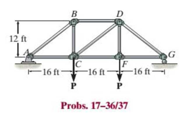
Chapter 17.3, Problem 37P
The members of the truss are assumed to be pin connected. If member BD is an A992 steel rod of radius 2 in., determine the maximum load P that can be supported by the truss without causing the member to buckle.
17–37. Solve Prob. 17–36 for member AB, which has a radius of 2 in.
Expert Solution & Answer
Want to see the full answer?
Check out a sample textbook solution
Students have asked these similar questions
handwritten solutions only, please!
On from the equation:
2
u = C₁ + C₂ Y + Czy + Cu y³
Find C₁, C₂, C3 and Cy Using these following
Cases :
(a)
4=0
at
y=0
(b)
U = U∞
at y = 8
du
(c)
at
Y = S
ду
--y.
ди
= 0
at
y = 0
буг
I need help with a MATLAB code. I am trying to solve this question. Based on the Mars powered landing scenariosolve Eq. (14) via convex programming. Report the consumed fuel, and discuss the results with relevant plots. I am using the following MATLAB code and getting an error. I tried to fix the error and I get another one saying something about log and exp not being convex. Can you help fix my code and make sure it works.
The error is CVX Warning: Models involving "log" or other functions in the log, exp, and entropy family are solved using an experimental successive approximation method. This method is slower and less reliable than the method CVX employs for other models. Please see the section of the user's guide entitled The successive approximation method for more details about the approach, and for instructions on how to suppress this warning message in the future.Error using .* (line 173)Disciplined convex programming error: Cannot perform the operation:…
Chapter 17 Solutions
Statics and Mechanics of Materials (5th Edition)
Ch. 17.3 - A 50-in.-long steel rod has a diameter of 1 in....Ch. 17.3 - A 12-ft wooden rectangular column has the...Ch. 17.3 - Prob. 3FPCh. 17.3 - A steel pipe is fixed supported at its ends. If it...Ch. 17.3 - Determine the maximum force P that can be...Ch. 17.3 - The A992 steel rod BC has a diameter of 50 mm and...Ch. 17.3 - Determine the critical buckling load for the...Ch. 17.3 - Prob. 2PCh. 17.3 - The aircraft link is made from an A992 steel rod....Ch. 17.3 - Rigid bars AB and BC are pin connected at B. If...
Ch. 17.3 - A 2014-T6 aluminum alloy column has a length of 6...Ch. 17.3 - Prob. 6PCh. 17.3 - Prob. 7PCh. 17.3 - Prob. 8PCh. 17.3 - A steel column has a length of 9 m and is fixed at...Ch. 17.3 - A steel column has a length of 9 m and is pinned...Ch. 17.3 - The A992 steel angle has a cross-sectional area of...Ch. 17.3 - The 50-mm-diameter C86100 bronze rod is fixed...Ch. 17.3 - Determine the maximum load P the frame can support...Ch. 17.3 - Prob. 14PCh. 17.3 - Prob. 15PCh. 17.3 - An A992 steel W200 46 column of length 9 m is...Ch. 17.3 - Prob. 17PCh. 17.3 - Prob. 18PCh. 17.3 - Prob. 19PCh. 17.3 - Prob. 20PCh. 17.3 - Prob. 21PCh. 17.3 - The deck is supported by the two 40-mm-square...Ch. 17.3 - Prob. 23PCh. 17.3 - Prob. 24PCh. 17.3 - Prob. 25PCh. 17.3 - Prob. 26PCh. 17.3 - Prob. 27PCh. 17.3 - The linkage is made using two A992 steel rods,...Ch. 17.3 - The linkage is made using two A-36 steel rods,...Ch. 17.3 - The linkage is made using two A-36 steel rods,...Ch. 17.3 - The steel bar AB has a rectangular cross section....Ch. 17.3 - Determine if the frame can support a load of P =...Ch. 17.3 - Determine the maximum allowable load P that can be...Ch. 17.3 - Prob. 34PCh. 17.3 - Prob. 35PCh. 17.3 - The members of the truss are assumed to be pin...Ch. 17.3 - The members of the truss are assumed to be pin...Ch. 17.3 - The truss is made from A992 steel bars, each of...Ch. 17.3 - The truss is made from A992 steel bars, each of...Ch. 17.3 - The steel bar AB of the frame is assumed to be pin...Ch. 17.3 - Prob. 41PCh. 17.3 - Prob. 42PCh. 17.3 - Prob. 43PCh. 17.3 - Prob. 44PCh. 17.3 - Consider an ideal column as in Fig. 1710d, having...Ch. 17.4 - Prob. 46PCh. 17.4 - Prob. 47PCh. 17.4 - The W10 12 structural A-36 steel column is used...Ch. 17.4 - The aluminum column is fixed at the bottom and...Ch. 17.4 - Prob. 50PCh. 17.4 - The aluminum rod is fixed at its base and free and...Ch. 17.4 - Prob. 52PCh. 17.4 - Prob. 53PCh. 17.4 - Prob. 54PCh. 17.4 - The wood column is pinned at its base and top....Ch. 17.4 - Prob. 56PCh. 17.4 - Prob. 57PCh. 17.4 - Prob. 58PCh. 17.4 - Prob. 59PCh. 17.4 - Prob. 60PCh. 17.4 - Prob. 61PCh. 17.4 - Prob. 62PCh. 17.4 - The W14 53 column is fixed at its base and free...Ch. 17.4 - Prob. 64PCh. 17 - The wood column is 4 m long and is required to...Ch. 17 - Prob. 2RPCh. 17 - A steel column has a length of 5 m and is free at...Ch. 17 - Prob. 4RPCh. 17 - Prob. 5RPCh. 17 - If P = 15 kip, determine the required minimum...Ch. 17 - Prob. 7RPCh. 17 - The W200 46 wide-flange A992-steel column can be...Ch. 17 - The wide-flange A992 steel column has the cross...Ch. 17 - The wide-flange A992 steel column has the cross...
Knowledge Booster


Learn more about
Need a deep-dive on the concept behind this application? Look no further. Learn more about this topic, mechanical-engineering and related others by exploring similar questions and additional content below.Similar questions
- Note: please use integration for parabolic volume (Vp) of the fluid displaced due to rotation. (Make it simpe as possible to follow in the working out). Provide a clear, step-by-step simplified handwritten solution (with no extra explanations) that is entirely produced by hand without any AI help. I require an expert-level answer, and I will assess it based on the quality and accuracy of the work, referring to the attached image for additional guidance. Make sure every detail is carefully verified for correctness before you submit. Thanks!.arrow_forwardNote: use centroid method please Provide a clear, step-by-step simplified handwritten solution (with no extra explanations) that is entirely produced by hand without any AI help. I require an expert-level answer, and I will assess it based on the quality and accuracy of the work, referring to the attached image for additional guidance. Make sure every detail is carefully verified for correctness before you submit. Thanks!.arrow_forwardCalculate the cutting time for a 4 in length of cut, given that the feed rate is 0.030 ipr at a speed of 90 fpm.arrow_forward
- for the values: M1=0.41m, M2=1.8m, M3=0.56m, please account for these in the equations. also please ensure that the final answer is the flow rate in litres per second for each part. please use bernoullis equation where needed if an empirical solutions i srequired. also The solutions should include, but not be limited to, the equations used tosolve the problems, the charts used to solve the problems, detailed working,choice of variables, the control volume considered, justification anddiscussion of results etc.If determining the friction factor, the use of both Moody chart and empiricalequations should be used to verify the validity of the valuearrow_forwardSolve this problem and show all of the workarrow_forwardSolve this problem and show all of the workarrow_forward
- Problem 2: An athlete, starting from rest, pulls handle A to the left with a constant force of P = 150 [N]. Knowing that after the handle A has been pulled 0.5 [m], its velocity is 5 [m/s] to the left, determine: a) A position constraint equation using the given coordinate system. b) An acceleration constraint equation. c) The acceleration of A using kinematics equations. d) The acceleration of B using your constraint equation. e) How much weight (magnitude) the athlete is lifting in pounds using Newton's 2nd Law. You must draw a FBD and KD of the circled assembly, assuming the pulleys are massless. Note: 1 [lbf] = 4.448 [N]. ХА Увarrow_forwardProblem 1: For each of the following images, draw a complete FBD and KD for the specified objects. Then write the equations of motion using variables for all unknowns (e.g., mass, friction coefficient, etc.), plugging in kinematic expressions and simplifying where appropriate. Assume motion in all cases, so any friction would be kinetic. M (a) Blocks A & B (Be careful with acceleration of B relative to accelerating block A) 30° (b) Block A being pulled up my motor M (use rotated rectangular coordinate system) 20° (c) Ball at C, top of swing (use path coordinates) (d) Parasailer/Person (use polar coordinates)arrow_forwardwhere M1=0.41m, M2=1.8m, M3=0.56m, please use bernoulis equation where necessary and The solutions should include, but not be limited to, the equations used tosolve the problems, the charts used to solve the problems, detailed working,choice of variables, the control volume considered, justification anddiscussion of results etc.If determining the friction factor, the use of both Moody chart and empiricalequations should be used to verify the validity of the value.arrow_forward
- Q3. The attachment shown in Fig.2 is made of 1040 HR. Design the weldment (give the pattern, electrode number, type of weld, length of weld, and leg size). All dimensions in mm 120 Fig.2 12 17 b =7.5 5 kN 60 60°arrow_forward15 mm DA 100 mm 50 mm Assuming the load applied P 80 kN. Determine the maximum stress in the bar shown assuming the diameter of the whole A is DA = 25 mm.arrow_forwarduse engineering economic tables, show full solutionarrow_forward
arrow_back_ios
SEE MORE QUESTIONS
arrow_forward_ios
Recommended textbooks for you
 Mechanics of Materials (MindTap Course List)Mechanical EngineeringISBN:9781337093347Author:Barry J. Goodno, James M. GerePublisher:Cengage Learning
Mechanics of Materials (MindTap Course List)
Mechanical Engineering
ISBN:9781337093347
Author:Barry J. Goodno, James M. Gere
Publisher:Cengage Learning
Engineering Basics - Statics & Forces in Equilibrium; Author: Solid Solutions - Professional Design Solutions;https://www.youtube.com/watch?v=dQBvQ2hJZFg;License: Standard YouTube License, CC-BY