
VECTOR MECHANICS FOR ENGINEERS W/CON >B
12th Edition
ISBN: 9781260804638
Author: BEER
Publisher: MCG
expand_more
expand_more
format_list_bulleted
Concept explainers
Videos
Textbook Question
Chapter 17.1, Problem 17.9P
The 10-in.-radius brake drum is attached to a larger flywheel which is not shown. The total mass moment of inertia of the flywheel and drum is 16 lb·ft·s2 and the coefficient of kinetic friction between the drum and the brake shoe is 0.40. Knowing that the initial angular velocity is 240 rpm clockwise, determine the force that must be exerted by the hydraulic cylinder if the system is to stop in 75 revolutions.
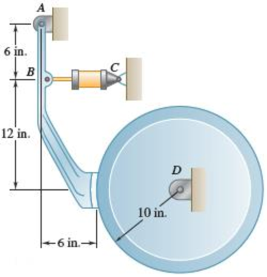
Fig. P17.9
Expert Solution & Answer
Want to see the full answer?
Check out a sample textbook solution
Students have asked these similar questions
A 22-lb block B rests as shown on a 28-lb bracket A. The coefficients of friction are μs=0.30μs=0.30 and μk=0.25μk=0.25 between block B and bracket A, and there is no friction in the pulley or between the bracket and the horizontal surface. solved in a previous part. max weight of block C if block B is not to slide on bracket A is 5.045 lbs. Please solve for the acceleration of each Block
Test 1 .DOCX * A
File Edit View
Tools Help
INDUSTRIAL ENGINEERING PROGRAMME
IMB 411-INDUSTRIAL LOGISTICS
TEST 1- SEPTEMBER 12, 2012
Instructions: Answer all questions. Time allowed is 1.5 hours. Identify your script with your
student number ONLY (Do not write your name).
1. Define the following terms
(i) Logistics management
(ii) Supply chain management
(iii) Vertical integration in a supply chain
(3 Marks)
(3 Marks)
(3 Marks)
2. (a) Using examples of your choice, briefly discuss the following levels of customer
service
(1) Pre-transaction elements
(ii) Transaction elements
(4 Marks)
(4 Marks)
(iii) Post-transaction elements
(4 Marks)
(b) "The challenge facing Dumelang Enterprise (Pty) Ltd is to establish the real
profitability of their customers and to develop service strategies that will improve the
profitability of all customers". As a logistics consultant, briefly discuss how you can
advise Dumelang's customer service management.
3. (a) List the three main forms of inventory in a…
It is decided to install several single-jet Pelton wheels to produce a total power of 18 MW. The
available head is 246 m. The wheel rotational speed is 650 rpm and the speed ratio (❤) = 0.46.
The diameter of the nozzle (jet) is limited to be 0.167 m with a Cv of 0.95. The efficiency of each
turbine is 87%. Determine: (1) The number of Pelton wheels to be used, and (2) The bucket
angle.
Chapter 17 Solutions
VECTOR MECHANICS FOR ENGINEERS W/CON >B
Ch. 17.1 - A round object of mass m and radius r is released...Ch. 17.1 - Prob. 17.2CQCh. 17.1 - Prob. 17.3CQCh. 17.1 - Prob. 17.4CQCh. 17.1 - Slender bar A is rigidly connected to a massless...Ch. 17.1 - A 200-kg flywheel is at rest when a constant 300...Ch. 17.1 - The rotor of an electric motor has an angular...Ch. 17.1 - Prob. 17.3PCh. 17.1 - Two disks of the same material are attached to a...Ch. 17.1 - The flywheel of a punching machine has a weight of...
Ch. 17.1 - Prob. 17.6PCh. 17.1 - Prob. 17.7PCh. 17.1 - Prob. 17.8PCh. 17.1 - The 10-in.-radius brake drum is attached to a...Ch. 17.1 - Prob. 17.10PCh. 17.1 - Each of the gears A and B has a mass of 10 kg and...Ch. 17.1 - Solve Prob. 17.11, assuming that the 6 Nm couple...Ch. 17.1 - Prob. 17.13PCh. 17.1 - The double pulley shown has a mass of 15 kg and a...Ch. 17.1 - Gear A has a mass of 1 kg and a radius of gyration...Ch. 17.1 - A slender rod of length l and mass m is pivoted...Ch. 17.1 - The 15-kg rear hatch of a vehicle opens as shown...Ch. 17.1 - A slender 9-lb rod can rotate in a vertical plane...Ch. 17.1 - An adapted golf device attaches to a wheelchair to...Ch. 17.1 - A 10-kg storm window measuring 900 1500 mm is...Ch. 17.1 - A collar with a mass of 1 kg is rigidly attached...Ch. 17.1 - A collar with a mass of 1 kg is rigidly attached...Ch. 17.1 - Two identical slender rods AB and BC are welded...Ch. 17.1 - Prob. 17.24PCh. 17.1 - A 100-kg solid cylindrical disk, 800 mm in...Ch. 17.1 - Prob. 17.26PCh. 17.1 - Greek engineers had the unenviable task of moving...Ch. 17.1 - A small sphere of mass m and radius r is released...Ch. 17.1 - Prob. 17.29PCh. 17.1 - A half-cylinder with mass m and radius r is...Ch. 17.1 - Prob. 17.31PCh. 17.1 - Two uniform cylinders, each of weight W = 14 lb...Ch. 17.1 - Prob. 17.33PCh. 17.1 - A bar of mass m = 5 kg is held as shown between...Ch. 17.1 - The 1.5-kg uniform slender bar AB is connected to...Ch. 17.1 - The motion of the uniform rod AB is guided by...Ch. 17.1 - Prob. 17.37PCh. 17.1 - Prob. 17.38PCh. 17.1 - The ends of a 9-lb rod AB are constrained to move...Ch. 17.1 - The mechanism shown is one of two identical...Ch. 17.1 - The mechanism shown is one of two identical...Ch. 17.1 - Each of the two rods shown is of length L = 1 m...Ch. 17.1 - The 4-kg rod AB is attached to a collar of...Ch. 17.1 - If in Prob. 17.43 the angular velocity of the...Ch. 17.1 - The uniform rods AB and BC are of mass 3 kg and 8...Ch. 17.1 - The uniform rods AB and BC weigh 2.4 kg and 4 kg,...Ch. 17.1 - The 80-mm-radius gear shown has a mass of 5 kg and...Ch. 17.1 - Prob. 17.48PCh. 17.1 - Three shafts and four gears are used to form a...Ch. 17.1 - The experimental setup shown is used to measure...Ch. 17.1 - Prob. 17.51PCh. 17.2 - The 350-kg flywheel of a small hoisting engine has...Ch. 17.2 - Prob. 17.2IMDCh. 17.2 - Prob. 17.3IMDCh. 17.2 - Prob. 17.52PCh. 17.2 - A bolt located 2 in. from the center of an...Ch. 17.2 - A small grinding wheel is attached to the shaft of...Ch. 17.2 - A uniform 144-lb cube is attached to a uniform...Ch. 17.2 - Prob. 17.56PCh. 17.2 - Prob. 17.57PCh. 17.2 - Prob. 17.58PCh. 17.2 - Prob. 17.59PCh. 17.2 - Each of the double pulleys shown has a centroidal...Ch. 17.2 - Each of the gears A and B has a mass of 675 g and...Ch. 17.2 - Two identical uniform cylinders of mass m and...Ch. 17.2 - Two identical 16-lb uniform cylinders of radius r...Ch. 17.2 - Prob. 17.64PCh. 17.2 - Prob. 17.65PCh. 17.2 - Show that, when a rigid body rotates about a fixed...Ch. 17.2 - Prob. 17.68PCh. 17.2 - A flywheel is rigidly attached to a 1.5-in.-radius...Ch. 17.2 - A wheel of radius r and centroidal radius of...Ch. 17.2 - Prob. 17.71PCh. 17.2 - 17.72 and 17.73The 3-lb carriage C is supported as...Ch. 17.2 - Prob. 17.73PCh. 17.2 - Two uniform cylinders, each of mass m = 6 kg and...Ch. 17.2 - Prob. 17.75PCh. 17.2 - Prob. 17.76PCh. 17.2 - A sphere of radius r and mass m is projected along...Ch. 17.2 - A bowler projects an 8.5-in.-diameter ball...Ch. 17.2 - Prob. 17.79PCh. 17.2 - A satellite has a total weight (on Earth) of 250...Ch. 17.2 - Two 10-lb disks and a small motor are mounted on a...Ch. 17.2 - Prob. 17.82PCh. 17.2 - Prob. 17.83PCh. 17.2 - Prob. 17.84PCh. 17.2 - Prob. 17.85PCh. 17.2 - Prob. 17.86PCh. 17.2 - The 30-kg uniform disk A and the bar BC are at...Ch. 17.2 - Prob. 17.88PCh. 17.2 - A 1.8-kg collar A and a 0.7-kg collar B can slide...Ch. 17.2 - Prob. 17.90PCh. 17.2 - A small 4-lb collar C can slide freely on a thin...Ch. 17.2 - Rod AB has a weight of 6 lb and is attached to a...Ch. 17.2 - A 3-kg uniform cylinder A can roll without sliding...Ch. 17.2 - The 4-kg cylinder B and the 3-kg wedge A are at...Ch. 17.2 - The 6-lb steel cylinder A of radius r and the...Ch. 17.3 - A uniform slender rod AB of mass m is at rest on a...Ch. 17.3 - Prob. 17.5IMDCh. 17.3 - Prob. 17.6IMDCh. 17.3 - At what height h above its center G should a...Ch. 17.3 - A bullet weighing 0.08 lb is fired with a...Ch. 17.3 - In Prob. 17.97, determine (a) the required...Ch. 17.3 - A 16-lb wooden panel is suspended from a pin...Ch. 17.3 - Prob. 17.100PCh. 17.3 - A 45-g bullet is fired with a velocity of 400 m/s...Ch. 17.3 - A 45-g bullet is fired with a velocity of 400 m/s...Ch. 17.3 - The tire shown has a radius R = 300 mm and a...Ch. 17.3 - Prob. 17.104PCh. 17.3 - A uniform slender rod AB of mass m is at rest on a...Ch. 17.3 - A uniform slender rod AB is at rest on a...Ch. 17.3 - A bullet of mass m is fired with a horizontal...Ch. 17.3 - Determine the height h at which the bullet of...Ch. 17.3 - A uniform slender bar of length L = 200 mm and...Ch. 17.3 - A uniform slender rod of length L is dropped onto...Ch. 17.3 - A uniform slender rod AB has a mass m, a length L,...Ch. 17.3 - You have been hired to design a baseball catcher...Ch. 17.3 - The trapeze/lanyard air drop (t/LAD) launch is a...Ch. 17.3 - The uniform rectangular block shown is moving...Ch. 17.3 - The 40-kg gymnast drops from her maximum height of...Ch. 17.3 - A uniform slender rod AB of length L = 600 mm is...Ch. 17.3 - Prob. 17.118PCh. 17.3 - A 1-oz bullet is fired with a horizontal velocity...Ch. 17.3 - For the beam of Prob. 17.119, determine the...Ch. 17.3 - Prob. 17.121PCh. 17.3 - Prob. 17.122PCh. 17.3 - A slender rod AB is released from rest in the...Ch. 17.3 - Prob. 17.124PCh. 17.3 - Block A has a mass m and is attached to a cord...Ch. 17.3 - Prob. 17.126PCh. 17.3 - 17.127 and 17.128Member ABC has a mass of 2.4 kg...Ch. 17.3 - 17.127 and 17.128Member ABC has a mass of 2.4 kg...Ch. 17.3 - Prob. 17.129PCh. 17.3 - Prob. 17.130PCh. 17.3 - A small rubber ball of radius r is thrown against...Ch. 17.3 - Sphere A of mass m and radius r rolls without...Ch. 17.3 - In a game of pool, ball A is rolling without...Ch. 17 - A uniform disk, initially at rest and of constant...Ch. 17 - The 8-in.-radius brake drum is attached to a...Ch. 17 - A uniform slender rod is placed at corner B and is...Ch. 17 - The motion of the slender 250-mm rod AB is guided...Ch. 17 - A baseball attachment that helps people with...Ch. 17 - Disks A and B are made of the same material, are...Ch. 17 - Disks A and B are made of the same material, are...
Additional Engineering Textbook Solutions
Find more solutions based on key concepts
This optional Google account security feature sends you a message with a code that you must enter, in addition ...
SURVEY OF OPERATING SYSTEMS
Assume a telephone signal travels through a cable at two-thirds the speed of light. How long does it take the s...
Electric Circuits. (11th Edition)
What are the design issues for character string types?
Concepts Of Programming Languages
17–1C A high-speed aircraft is cruising in still air. How does the temperature of air at the nose of the aircra...
Thermodynamics: An Engineering Approach
How is the hydrodynamic entry length defined for flow in a pipe? Is the entry length longer in laminar or turbu...
Fluid Mechanics: Fundamentals and Applications
The solid steel shaft AC has a diameter of 25 mm and is supported by smooth bearings at D and E. It is coupled ...
Mechanics of Materials (10th Edition)
Knowledge Booster


Learn more about
Need a deep-dive on the concept behind this application? Look no further. Learn more about this topic, mechanical-engineering and related others by exploring similar questions and additional content below.Similar questions
- (I) [40 Points] Using centered finite difference approximations as done in class, solve the equation for O: d20 dx² + 0.010+ Q=0 subject to the boundary conditions shown in the stencil below. Do this for two values of Q: (a) Q = 0.3, and (b) Q= √(0.5 + 2x)e-sinx (cos(5x)+x-0.5√1.006-x| + e −43*|1+.001+x* | * sin (1.5 − x) + (cosx+0.001 + ex-1250+ sin (1-0.9x)|) * x - 4.68x4. For Case (a) (that is, Q = 0.3), use the stencil in Fig. 1. For Case (b), calculate with both the stencils in Fig. 1 and Fig 2. For all the three cases, show a table as well as a plot of O versus x. Discuss your results. Use MATLAB and hand in the MATLAB codes. 1 0=0 x=0 2 3 4 0=1 x=1 Fig 1 1 2 3 4 5 6 7 8 9 10 11 0=0 x=0 0=1 x=1 Fig 2arrow_forwardFig 2 (II) [60 Points] Using centered finite difference approximation as done in class, solve the equation: 020 020 + მx2 მy2 +0.0150+Q=0 subject to the boundary conditions shown in the stencils below. Do this for two values of Q: (a) Q = 0.3, and (b) Q = 10.5x² + 1.26 * 1.5 x 0.002 0.008. For Case (a) (that is, Q = 0.3) use Fig 3. For Case (b), use both Fig. 3 and Fig 4. For all the three cases, show a table as well as the contour plots of versus (x, y), and the (x, y) heat flux values at all the nodes on the boundaries x = 1 and y = 1. Discuss your results. Use MATLAB and hand in the MATLAB codes. (Note that the domain is (x, y)e[0,1] x [0,1].) 0=0 0=0 4 8 12 16 10 Ꮎ0 15 25 9 14 19 24 3 11 15 0=0 8-0 0=0 3 8 13 18 23 2 6 сл 5 0=0 10 14 6 12 17 22 1 6 11 16 21 13 e=0 Fig 3 Fig 4 Textbook: Numerical Methods for Engineers, Steven C. Chapra and Raymond P. Canale, McGraw-Hill, Eighth Edition (2021).arrow_forwardShip construction question. Sketch and describe the forward arrangements of a ship. Include componets of the structure and a explanation of each part/ term. Ive attached a general fore end arrangement. Simplfy construction and give a brief describion of the terms.arrow_forward
- Problem 1 Consider R has a functional relationship with variables in the form R = K xq xx using show that n ✓ - (OR 1.) = i=1 2 Их Ux2 Ихэ 2 (177)² = ² (1)² + b² (12)² + c² (1)² 2 UR R x2 x3arrow_forward4. Figure 3 shows a crank loaded by a force F = 1000 N and Mx = 40 Nm. a. Draw a free-body diagram of arm 2 showing the values of all forces, moments, and torques that act due to force F. Label the directions of the coordinate axes on this diagram. b. Draw a free-body diagram of arm 2 showing the values of all forces, moments, and torques that act due to moment Mr. Label the directions of the coordinate axes on this diagram. Draw a free body diagram of the wall plane showing all the forces, torques, and moments acting there. d. Locate a stress element on the top surface of the shaft at A and calculate all the stress components that act upon this element. e. Determine the principal stresses and maximum shear stresses at this point at A.arrow_forward3. Given a heat treated 6061 aluminum, solid, elliptical column with 200 mm length, 200 N concentric load, and a safety factor of 1.2, design a suitable column if its boundary conditions are fixed-free and the ratio of major to minor axis is 2.5:1. (Use AISC recommended values and round the ellipse dimensions so that both axes are whole millimeters in the correct 2.5:1 ratio.)arrow_forward
- 1. A simply supported shaft is shown in Figure 1 with w₁ = 25 N/cm and M = 20 N cm. Use singularity functions to determine the reactions at the supports. Assume El = 1000 kN cm². Wo M 0 10 20 30 40 50 60 70 80 90 100 110 cm Figure 1 - Problem 1arrow_forwardPlease AnswerSteam enters a nozzle at 400°C and 800 kPa with a velocity of 10 m/s and leaves at 375°C and 400 kPa while losing heat at a rate of 26.5 kW. For an inlet area of 800 cm2, determine the velocity and the volume flow rate of the steam at the nozzle exit. Use steam tables. The velocity of the steam at the nozzle exit is m/s. The volume flow rate of the steam at the nozzle exit is m3/s.arrow_forward2. A support hook was formed from a rectangular bar. Find the stresses at the inner and outer surfaces at sections just above and just below O-B. -210 mm 120 mm 160 mm 400 N B thickness 8 mm = Figure 2 - Problem 2arrow_forward
arrow_back_ios
SEE MORE QUESTIONS
arrow_forward_ios
Recommended textbooks for you
 Elements Of ElectromagneticsMechanical EngineeringISBN:9780190698614Author:Sadiku, Matthew N. O.Publisher:Oxford University Press
 Mechanics of Materials (10th Edition)Mechanical EngineeringISBN:9780134319650Author:Russell C. HibbelerPublisher:PEARSON
 Thermodynamics: An Engineering ApproachMechanical EngineeringISBN:9781259822674Author:Yunus A. Cengel Dr., Michael A. BolesPublisher:McGraw-Hill Education
 Control Systems EngineeringMechanical EngineeringISBN:9781118170519Author:Norman S. NisePublisher:WILEY
 Mechanics of Materials (MindTap Course List)Mechanical EngineeringISBN:9781337093347Author:Barry J. Goodno, James M. GerePublisher:Cengage Learning
 Engineering Mechanics: StaticsMechanical EngineeringISBN:9781118807330Author:James L. Meriam, L. G. Kraige, J. N. BoltonPublisher:WILEY
Elements Of Electromagnetics
Mechanical Engineering
ISBN:9780190698614
Author:Sadiku, Matthew N. O.
Publisher:Oxford University Press
Mechanics of Materials (10th Edition)
Mechanical Engineering
ISBN:9780134319650
Author:Russell C. Hibbeler
Publisher:PEARSON
Thermodynamics: An Engineering Approach
Mechanical Engineering
ISBN:9781259822674
Author:Yunus A. Cengel Dr., Michael A. Boles
Publisher:McGraw-Hill Education
Control Systems Engineering
Mechanical Engineering
ISBN:9781118170519
Author:Norman S. Nise
Publisher:WILEY
Mechanics of Materials (MindTap Course List)
Mechanical Engineering
ISBN:9781337093347
Author:Barry J. Goodno, James M. Gere
Publisher:Cengage Learning
Engineering Mechanics: Statics
Mechanical Engineering
ISBN:9781118807330
Author:James L. Meriam, L. G. Kraige, J. N. Bolton
Publisher:WILEY
Mechanical Design (Machine Design) Clutches, Brakes and Flywheels Intro (S20 ME470 Class 15); Author: Professor Ted Diehl;https://www.youtube.com/watch?v=eMvbePrsT34;License: Standard Youtube License