
Concept explainers
Videos
In the diagram, Load A is rated at 10 amperes, 120 volts. Load B is rated at 5 amperes, 120 volts.
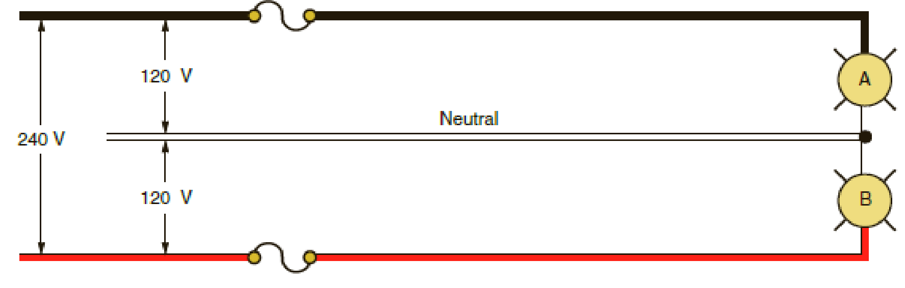
- a. When connected to the 3-wire branch circuit as indicated, how much current will flow in the neutral conductor? __________________
- b. If the neutral conductor should open, to what voltage would each load be subjected, assuming both loads were operating at the time the neutral conductor opened? Show all calculations.
a.
Find the amount of current that flows in a neutral conductor when a circuit is connected to a 3-wire branch circuit.
Answer to Problem 4R
The amount of current that flows in the neutral conductor is
Explanation of Solution
Given data:
The values of current and voltage at Load A are
The values of current and voltage at Load B are
The total voltage of the system is
Calculation:
From the given data, the values of current to Load A and Load B are not equal. Therefore, it is an unbalanced load.
For an unbalanced load, the current through the neutral conductor is calculated as follows:
Substitute
Conclusion:
Thus, the amount of current that flows in the neutral conductor is
b.
Find the voltage of each load when the neutral conductor is open.
Answer to Problem 4R
The voltage of Load A is
Explanation of Solution
Formula used:
Write an expression to calculate the resistance.
Here,
Calculation:
Substitute
Substitute
When the neutral conductor is open, Load A and Load B are connected in series. Therefore, the total resistance is calculated as follows:
Substitute
Rearrange equation (2) to find
Substitute
Rearrange equation (4) to find
For the series connected load, the current is same for both Load A and Load B.
Substitute
Substitute
Conclusion:
Thus, the voltage of Load A is
Want to see more full solutions like this?
Chapter 17 Solutions
Electrical Wiring: Residental - With Plans (Paperback) Package
Additional Engineering Textbook Solutions
BASIC BIOMECHANICS
Vector Mechanics For Engineers
Database Concepts (8th Edition)
Electric Circuits. (11th Edition)
Mechanics of Materials (10th Edition)
Starting Out with C++: Early Objects (9th Edition)


- I have uploaded the rules, please explain step by step and which rule you have appliedarrow_forwardI have uploaded the rules, please explain step by step and which rule you have appliedarrow_forwardUsing the CCS Compiler method to solve this question Write a PIC16F877A program that flash ON the 8-LED's connected to port-B by using two switches connected to port-D (Do & D₁) as shown in figure below, according to the following scenarios: (Hint: Use 500ms delay for each case with 4MHz frequency) 1. When Do=1 then B₁,B3,B7 are ON. 2. When Do 0 then Bo,B2, B4, B5, B6 are ON. 3. When D₁=1 then B4,B,,B6,B7 are ON. 4. When D₁-0 then Bo,B1,B2,B3 are ON.arrow_forward
- Use the ramp generator circuit in Fig. B2a to generate the waveform shown in Fig. B2b. Write four equations relating resistors R1, R2, R3, capacitor C and voltages Vs, VR and VA.to the waveform parameters T₁, T, Vcm and Vm- If R = R2 = R3, R₁ = 2R, C = 1 nF, Vcm = 2 V and Vm = 1 V, T₁ = 2 μs and T = 10 μs solve for the values of R, Vs, VR and VA using your equations from part a(i). VR C +VA R3 V₂ Vo мат R1 VsO+ V₁ R₂ Figure B2a Vout Vcm+Vm Vcm Vcm-Vm 0 T₁ T 2T time Figure B2barrow_forwardThe circuit in Figure B1a is a common analogue circuit block. Explain why you would need such a circuit. Draw another circuit in which you use the current flowing in this loop to bias a common source amplifier. This circuit is not ideal for standard CMOS technologies due to threshold shift. Why? Draw an improved version of this circuit to make it better. VDD (W)P MA M3. (), REF (쁜)~ M₁ M2 lout 시~ Rsarrow_forward23bcarrow_forward
- Draw the small-signal equivalent circuit of a single transistor amplifier given in figure B1b. Assume the current source to be ideal. Determine the Open-loop transfer function, pole frequency and gain-bandwidth product all in terms of transistor parameters 9m, To and CL. If the load capacitance is 1pF and the necessary unity gain frequency is 600MHz, find the gm for this transistor. V₁ V₁ CLarrow_forward23baarrow_forward23caarrow_forward
 EBK ELECTRICAL WIRING RESIDENTIALElectrical EngineeringISBN:9781337516549Author:SimmonsPublisher:CENGAGE LEARNING - CONSIGNMENT