
Concept explainers
(a)
Calculate the Fourier transform of the function shown in the given Figure.
(a)
Answer to Problem 1P
The Fourier transform for the function given in Figure is
Explanation of Solution
Given data:
Refer to Figure given in the textbook.
Formula used:
Write the general expression for the function
Write the general expression for definite integral
Calculation:
In the given Figure, the function
The end points of the function
The slope of the straight line is calculated as follows,
Substitute
Therefore, for the given Figure, the function
Applying equation (3) in equation (2) as follows,
Consider,
Write the general expression for integration by parts method as follows,
By applying integration by parts to equation (5),
Applying equation (6) in equation (5) as follows,
Consider,
Consider,
Substitute
Substitute equation (9) in equation (7) as follows,
The above equation as follows,
Substitute equation (10) in equation (4), and applying the limits as follows,
Conclusion:
Thus, the Fourier transform for the function given in Figure is
(b)
Calculate
(b)
Answer to Problem 1P
The function
Explanation of Solution
Given data:
Refer to Part (a).
Formula used:
Write the general expression for L’Hospital’s rule as follows,
Calculation:
Applying equation (12) to equation (11) when
The above equation becomes,
Conclusion:
Thus, the function
(c)
Plot
(c)
Answer to Problem 1P
The sketch for
Explanation of Solution
Given data:
Refer to Part (a),
Calculation:
Appling
Create a table as shown in below Table 1.
Table 1
| Angular Frequency | Function |
| –200 | 0.0785 |
| –190 | 0.1041 |
| –180 | 0.1063 |
| –170 | 0.0819 |
| –160 | 0.0336 |
| –150 | 0.0295 |
| –140 | 0.0943 |
| –130 | 0.1452 |
| –120 | 0.1678 |
| –110 | 0.1522 |
| –100 | 0.0951 |
| –90 | 0.0014 |
| –80 | 0.1161 |
| –70 | 0.2389 |
| –60 | 0.3457 |
| –50 | 0.4162 |
| –40 | 0.4354 |
| –30 | 0.3962 |
| –35 | 0.3012 |
| –15 | 0.1625 |
| 0 | 5.0000 (Original value is infinity, though for the instance consider one finite value as 5) |
| 10 | 0.1625 |
| 20 | 0.3012 |
| 30 | 0.3962 |
| 40 | 0.4354 |
| 50 | 0.4162 |
| 60 | 0.3457 |
| 70 | 0.2389 |
| 80 | 0.1161 |
| 90 | 0.0014 |
| 100 | 0.0951 |
| 110 | 0.1522 |
| 120 | 0.1678 |
| 130 | 0.1452 |
| 140 | 0.0943 |
| 150 | 0.0295 |
| 160 | 0.0336 |
| 170 | 0.0819 |
| 180 | 0.1063 |
| 190 | 0.1041 |
| 200 | 0.0785 |
Sketch the plot for various values of function
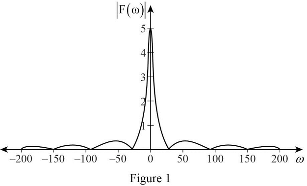
Conclusion:
Thus, the sketch for
Want to see more full solutions like this?
Chapter 17 Solutions
Electrical Circuits and Modified MasteringEngineering - With Access


- The state-space Jordan Canonical Form of the following system is: Y(s) 8-5 U(s) (+1)(+3) Select one: O a. -1 0 0 A = 0 -1 0 B: ... ... ... 0 0 C [4 1.5 1.5], D=0 b. -3 1 0 0 A = 0 -3 0 1 B ... 0 0 -1 C -4 -1.5 1.5], D=0 ○ C. -3 1 0 A = 0 -3 0 1 ,B= ... 0 0 ○ d. C [4 1.5 1.5], D=0 -3 1 0 0 A = 0 -3 0 1 , B: ... ... 0 0 -1 C [4 1.5 1.5], D=0 -4 1 If= x and (0): = then 2(t) is: -4 0 Select one: a. x2(t)=4te2t O b. x2(t) = e2t+2te2t Oc. 2(t)=-4te-21 Od. 2(t) e2-2te-2 =arrow_forwardThree speech signals are TDM multiplexed with a high-quanty music signal. It each speech signal is sampled at 16 kHz and PCM quantized by 8 bits/sample, while the music signal is sampled at 64 kHz with the same PCM quantizer. 1. Draw the block diagram of this TDM. 2. Calculate the output bit rate of this TDM.arrow_forward3- For the network below determine the value of R for maximum power to R (use Thevenin equivalent) and determine the value of maximum power R₁ 1.2Ω E + 12 V I D 10 A R₂60 6Ω Rarrow_forward
- Please solve this problem in detail to understandarrow_forwardQ3: (40 Marks) Single phase full bridge voltage source inverter has an RLC load with R-1002, L-31.5mH and C=112µF. The inverter frequency is 60Hz and de input voltage is 220V. (a) Express the instantaneous load current in Fourier series to third harmonic. (b) Calculate the RMS load current at the fundamental frequency (n=1). (c) Calculate the load power due to fundamental component (n=1).arrow_forward12.3 Express each of the waveforms in Fig. P12.3 (on page 667) in terms of step functions and then determine its Laplace transform. [Recall that the ramp function is related to the step function by r(t − T) = (t − T) u(t − T).] Assume that all waveforms are zero for t<0. - - -arrow_forward
- Evaluate each of the following integraarrow_forwardWith the aid of suitable diagrams, describe the benefits that antenna arrays have over singleelement antennas, with their applicationsarrow_forwardExplain what is meant by an electric dipole antenna, sketch its radiation pattern, state itsdirectivity and describe its main applicationsarrow_forward
- Estimate the length required for a half-waveelectric dipole antenna for transmitting/receiving EM waves at 800 MHz (this is in the UHFbandwidth of 470 to 860 MHz, used for UK TV transmissions).arrow_forwardIf the voltage waveform in Fig. 6.68 is applied to a 50-mH inductor, find the inductor current i(1). Assume i(0) = 0.arrow_forwardQ3/A 8-pole, 3-phase, 50 Hz induction motor, running at 725 r.p.m, rotor is star connected its resistance and reactance 0.25 and 1.5 ohm per phase, the emf between slip rings is 100, find the rotor current per phase, power factor, synchronous speed, slip and rotor frequencyarrow_forward
 Introductory Circuit Analysis (13th Edition)Electrical EngineeringISBN:9780133923605Author:Robert L. BoylestadPublisher:PEARSON
 Delmar's Standard Textbook Of ElectricityElectrical EngineeringISBN:9781337900348Author:Stephen L. HermanPublisher:Cengage Learning
 Programmable Logic ControllersElectrical EngineeringISBN:9780073373843Author:Frank D. PetruzellaPublisher:McGraw-Hill Education
 Fundamentals of Electric CircuitsElectrical EngineeringISBN:9780078028229Author:Charles K Alexander, Matthew SadikuPublisher:McGraw-Hill Education
 Electric Circuits. (11th Edition)Electrical EngineeringISBN:9780134746968Author:James W. Nilsson, Susan RiedelPublisher:PEARSON
 Engineering ElectromagneticsElectrical EngineeringISBN:9780078028151Author:Hayt, William H. (william Hart), Jr, BUCK, John A.Publisher:Mcgraw-hill Education,