
Concept explainers
Videos
The diagram of the conductor in the shape of a football, and draw with dozen electric field lines and two equipotential lines.
Explanation of Solution
Introduction:
If the body is negatively charged, then the lines of force are directed towards the body. The arrows on the lines of force represent the direction of the electric field.
The following picture represents the electric field lines of a charged body with charge
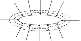
Figure (1)
The electric field lines are drawn in a way that they indicate the direction of the force due to the given field on the positive test charge. The equipotential lines are always perpendicular to the electric field lines.
Conclusion:
Thus, the required diagram is shown in figure (1).
Chapter 17 Solutions
Physics: Principles with Applications
Additional Science Textbook Solutions
Microbiology with Diseases by Body System (5th Edition)
Campbell Biology (11th Edition)
Human Anatomy & Physiology (2nd Edition)
Chemistry (7th Edition)
Organic Chemistry (8th Edition)
Chemistry: An Introduction to General, Organic, and Biological Chemistry (13th Edition)


- Hi! I need help with these calculations for part i and part k for a physics Diffraction Lab. We used a slit width 0.4 mm to measure our pattern.arrow_forwardExamine the data and % error values in Data Table 3 where the angular displacement of the simple pendulum decreased but the mass of the pendulum bob and the length of the pendulum remained constant. Describe whether or not your data shows that the period of the pendulum depends on the angular displacement of the pendulum bob, to within a reasonable percent error.arrow_forwardIn addition to the anyalysis of the graph, show mathematically that the slope of that line is 2π/√g . Using the slope of your line calculate the value of g and compare it to 9.8.arrow_forward
- An object is placed 24.1 cm to the left of a diverging lens (f = -6.51 cm). A concave mirror (f= 14.8 cm) is placed 30.2 cm to the right of the lens to form an image of the first image formed by the lens. Find the final image distance, measured relative to the mirror. (b) Is the final image real or virtual? (c) Is the final image upright or inverted with respect to the original object?arrow_forwardConcept Simulation 26.4 provides the option of exploring the ray diagram that applies to this problem. The distance between an object and its image formed by a diverging lens is 5.90 cm. The focal length of the lens is -2.60 cm. Find (a) the image distance and (b) the object distance.arrow_forwardPls help ASAParrow_forward
 College PhysicsPhysicsISBN:9781305952300Author:Raymond A. Serway, Chris VuillePublisher:Cengage Learning
 University Physics (14th Edition)PhysicsISBN:9780133969290Author:Hugh D. Young, Roger A. FreedmanPublisher:PEARSON
 Introduction To Quantum MechanicsPhysicsISBN:9781107189638Author:Griffiths, David J., Schroeter, Darrell F.Publisher:Cambridge University Press
 Physics for Scientists and EngineersPhysicsISBN:9781337553278Author:Raymond A. Serway, John W. JewettPublisher:Cengage Learning
 Lecture- Tutorials for Introductory AstronomyPhysicsISBN:9780321820464Author:Edward E. Prather, Tim P. Slater, Jeff P. Adams, Gina BrissendenPublisher:Addison-Wesley
 College Physics: A Strategic Approach (4th Editio...PhysicsISBN:9780134609034Author:Randall D. Knight (Professor Emeritus), Brian Jones, Stuart FieldPublisher:PEARSON