
Concept explainers
Find the member end moments and reactions for the frames.
Answer to Problem 31P
The reaction at point A
The end moment at the member
Explanation of Solution
Fixed end moment:
Formula to calculate the relative stiffness for fixed support
Formula to calculate the fixed moment for point load with equal length are
Formula to calculate the fixed moment for point load with unequal length are
Formula to calculate the fixed moment for UDL is
Formula to calculate the fixed moment for UVL are
Formula to calculate the fixed moment for deflection is
Calculation:
Consider the elastic modulus E of the frame is constant.
Show the free body diagram of the entire frame as in Figure 1.
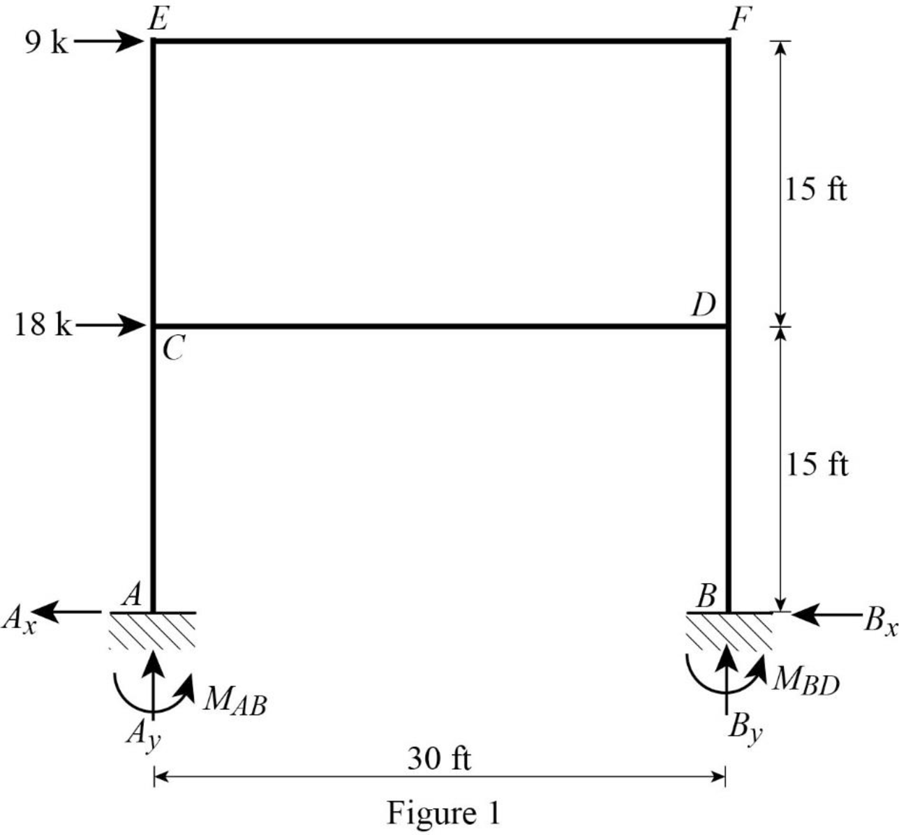
Refer Figure 1,
Calculate the relative stiffness
Calculate the relative stiffness
Calculate the distribution factor
Substitute
Calculate the distribution factor
Substitute
Calculate the distribution factor
Substitute
Check for sum of distribution factor as below:
Substitute
Hence, OK.
Calculate the distribution factor
Substitute
Calculate the distribution factor
Substitute
Check for sum of distribution factor as below:
Substitute
Hence, OK.
Calculate the distribution factor
Substitute
Calculate the distribution factor
Substitute
Check for sum of distribution factor as below:
Substitute
Hence, OK.
Calculate the distribution factor
Substitute
Calculate the distribution factor
Substitute
Calculate the distribution factor
Substitute
Check for sum of distribution factor as below:
Substitute
Hence, OK.
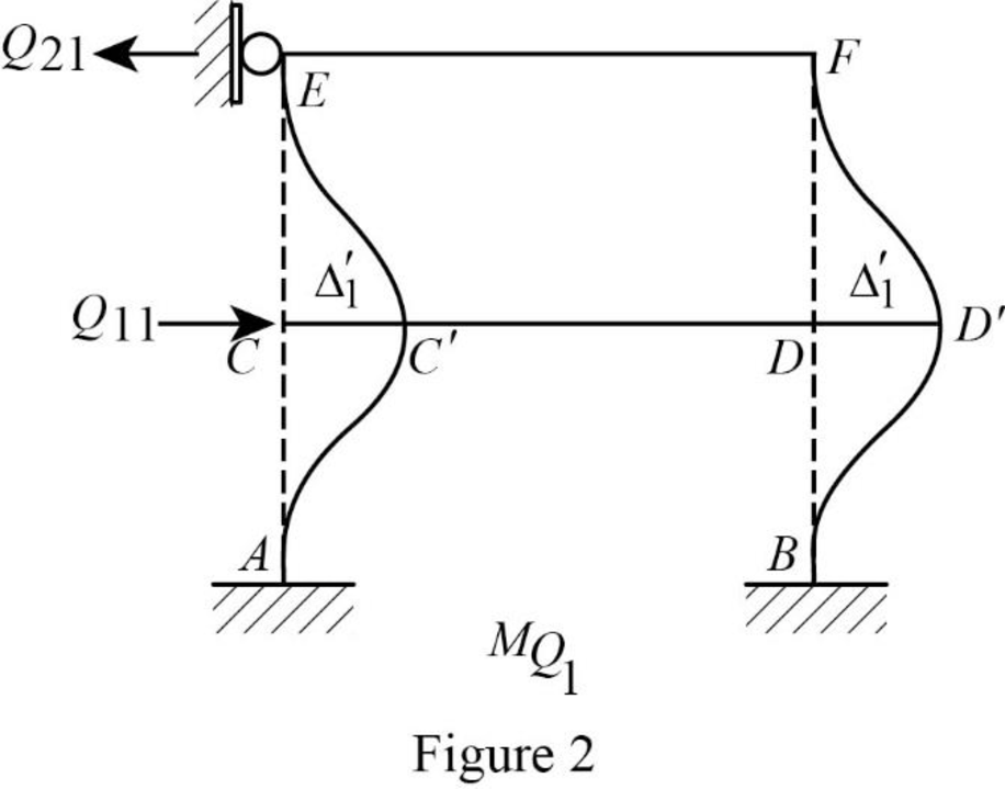
Show the translation
Write the expression to calculate the Fixed-end moment of the member.
Assume the Fixed-end moment of the members AC, CA, BD and DB as
Write the expression to calculate the Fixed-end moment of the member.
Assume the Fixed-end moment of the members CE, EC, DF and FD as
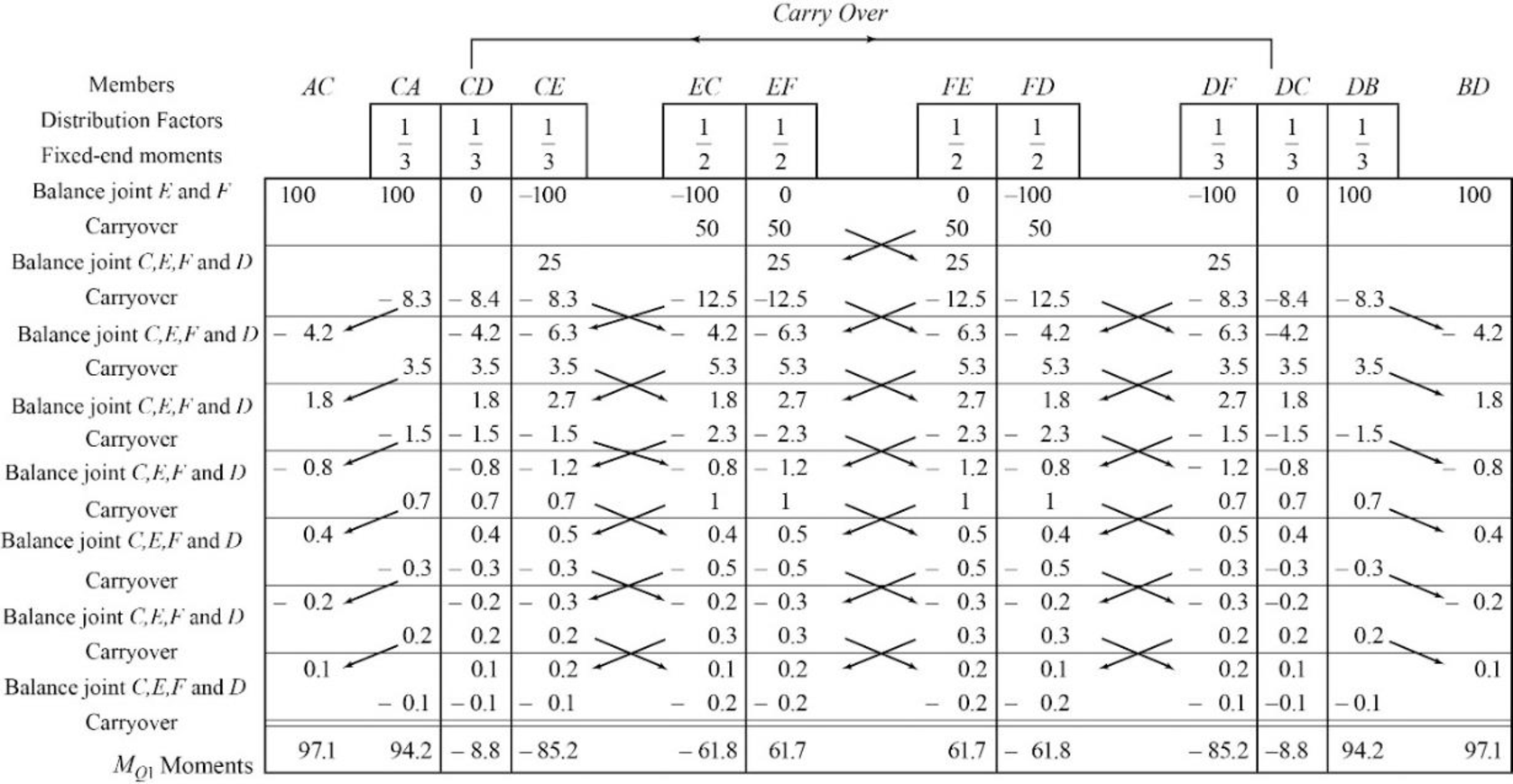
Show the calculation of
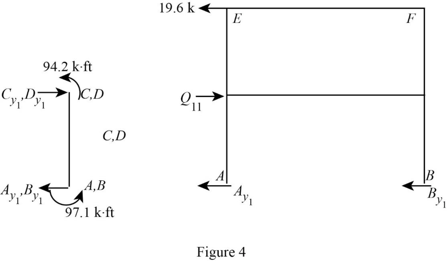
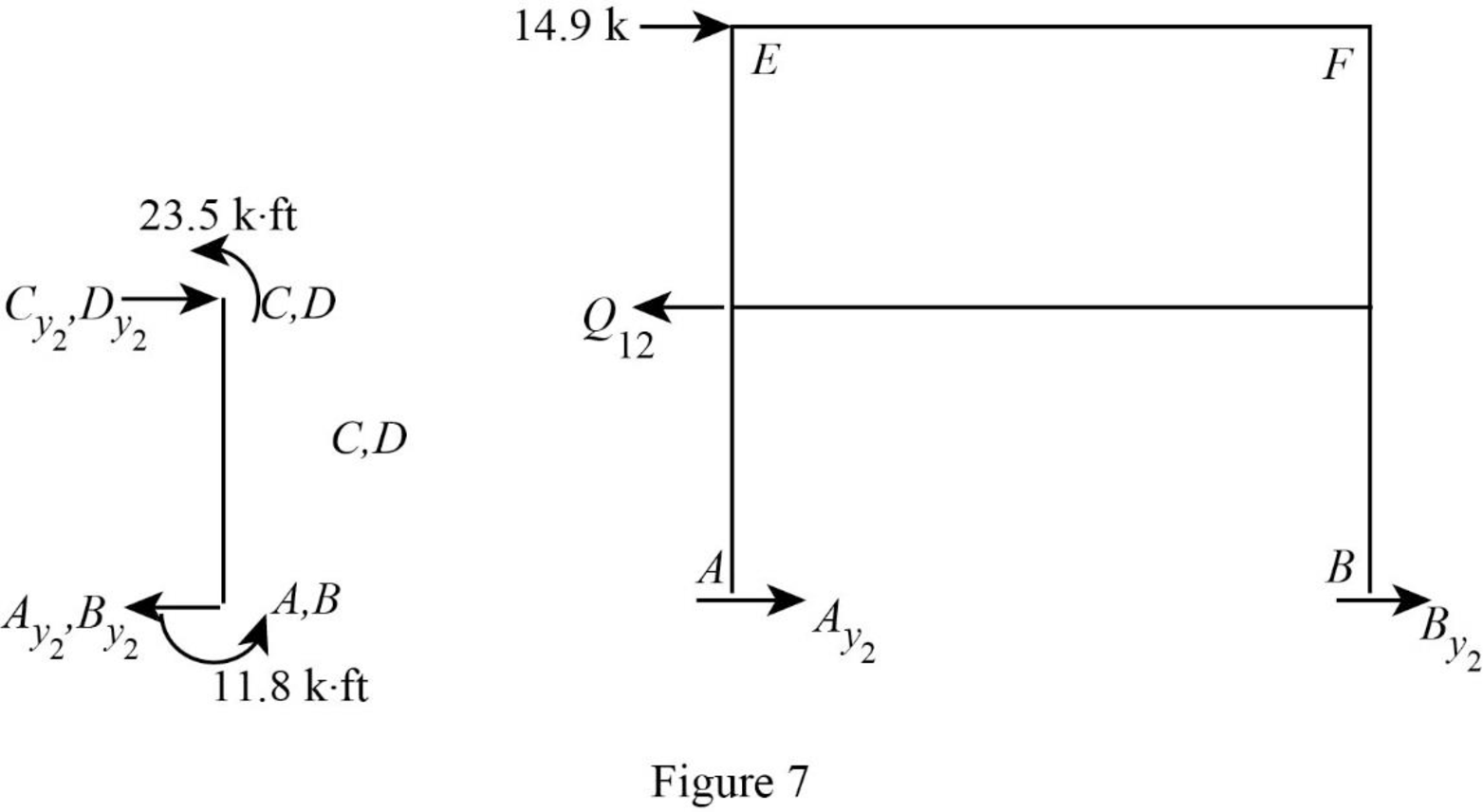
Show the free body diagram of the frame with unknown reaction
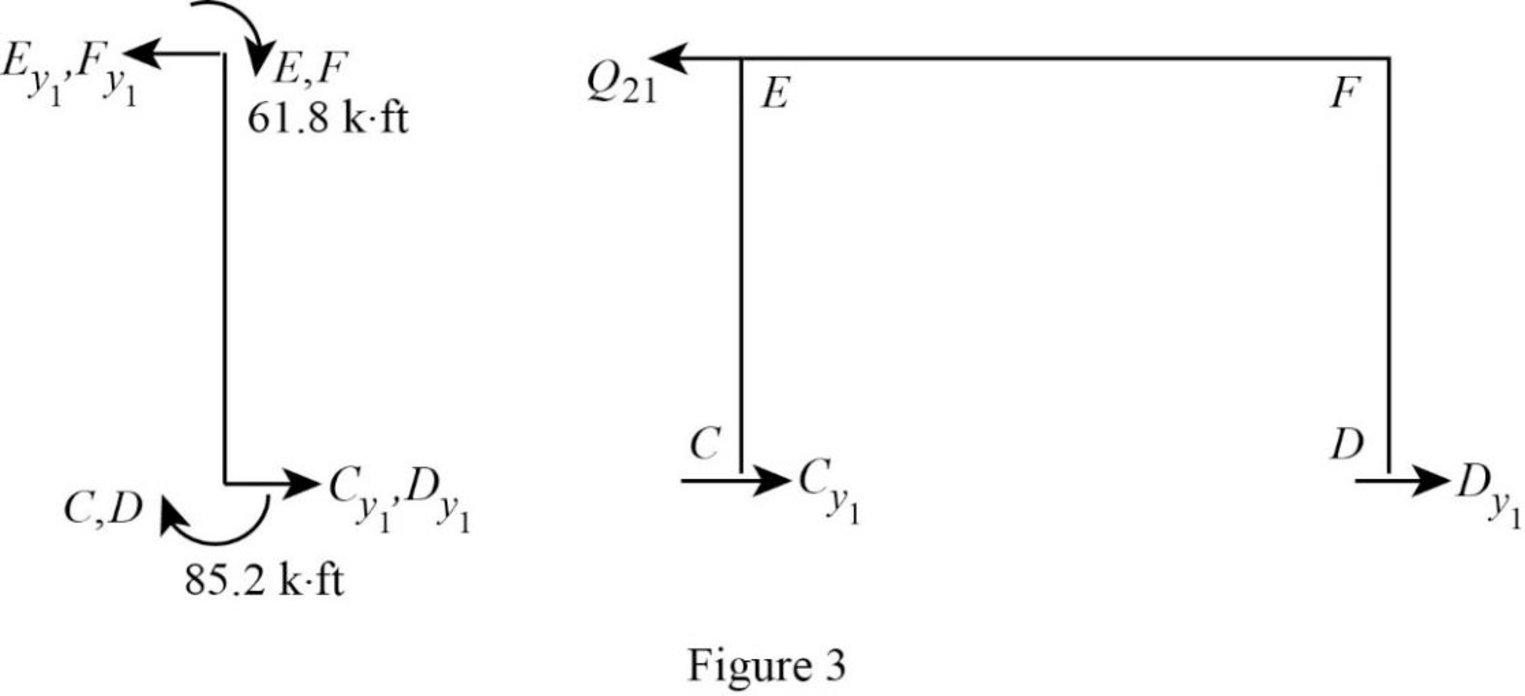
Consider member EC:
Calculate the horizontal reaction at the joint C by taking moment about point E.
Calculate the horizontal reaction at joint E by resolving the horizontal equilibrium.
Consider member FD:
Calculate the horizontal reaction at the joint D by taking moment about point F.
Calculate the horizontal reaction at joint F by resolving the horizontal equilibrium.
Calculate the reaction
Show the free body diagram of the frame with unknown reaction
Consider member AC:
Calculate the horizontal reaction at the joint A by taking moment about point C.
Calculate the horizontal reaction at joint C by resolving the horizontal equilibrium.
Consider member BD:
Calculate the horizontal reaction at the joint B by taking moment about point D.
Calculate the horizontal reaction at joint D by resolving the horizontal equilibrium.
Calculate the reaction
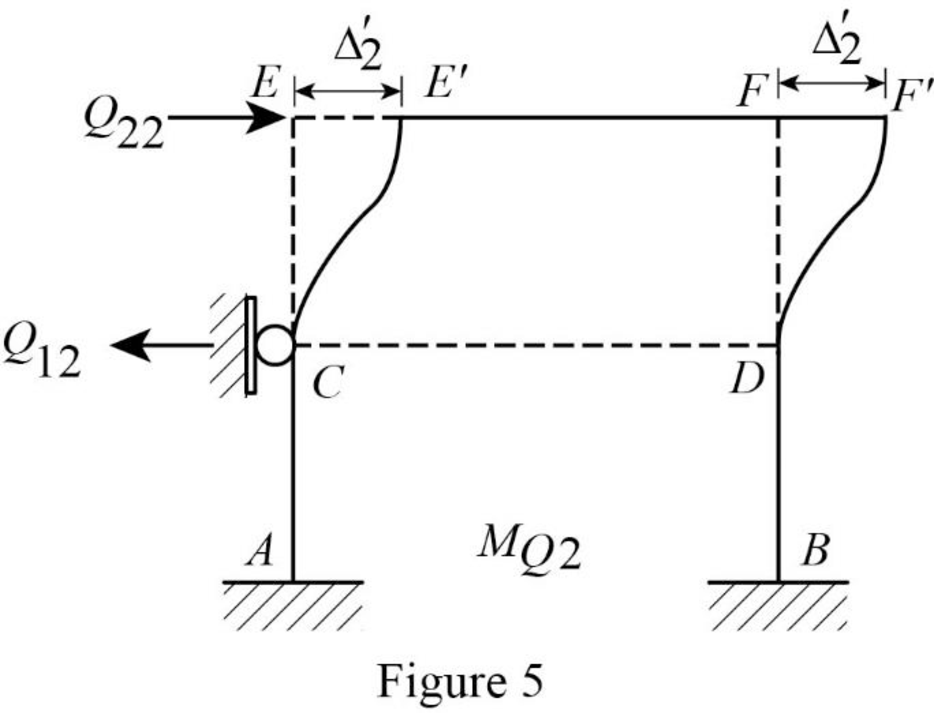
Show the translation
Write the expression to calculate the Fixed-end moment of the member.
Assume the Fixed-end moment of the members CE, EC, DF and FD as
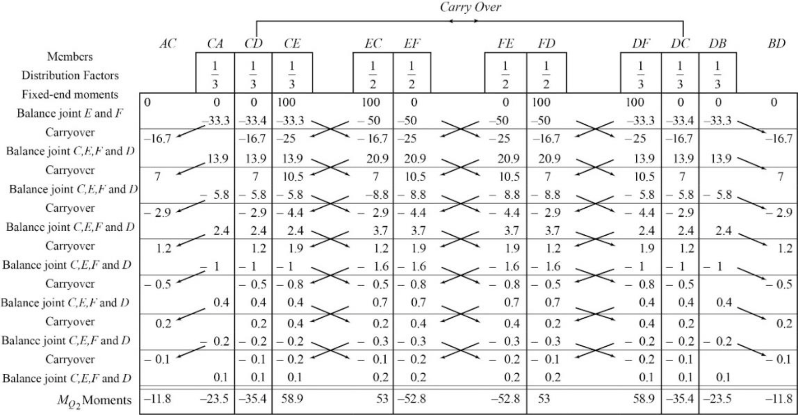
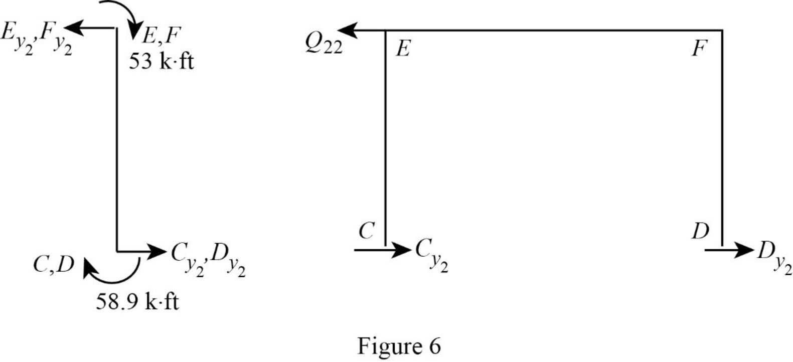
Show the calculation of
Show the free body diagram of the frame with unknown reaction
Consider member EC:
Calculate the horizontal reaction at the joint C by taking moment about point E.
Calculate the horizontal reaction at joint E by resolving the horizontal equilibrium.
Consider member FD:
Calculate the horizontal reaction at the joint D by taking moment about point F.
Calculate the horizontal reaction at joint F by resolving the horizontal equilibrium.
Calculate the reaction
Show the free body diagram of the frame with unknown reaction
Consider member AC:
Calculate the horizontal reaction at the joint A by taking moment about point C.
Calculate the horizontal reaction at joint C by resolving the horizontal equilibrium.
Consider member BD:
Calculate the horizontal reaction at the joint B by taking moment about point D.
Calculate the horizontal reaction at joint D by resolving the horizontal equilibrium.
Calculate the reaction
Write the equation by superimposing the horizontal forces at joints C,
Write the equation by superimposing the horizontal forces at joints E,
Calculate the value of
Calculate the actual member end moments of the member AC and BD:
Substitute
Calculate the actual member end moments of the member CA and DB:
Substitute
Calculate the actual member end moments of the member CD and DC:
Substitute
Calculate the actual member end moments of the member CE and DF:
Substitute
Calculate the actual member end moments of the member EC and FD:
Substitute
Calculate the actual member end moments of the member EC and FD:
Substitute
Show the section free body diagram of the member as in Figure 8.
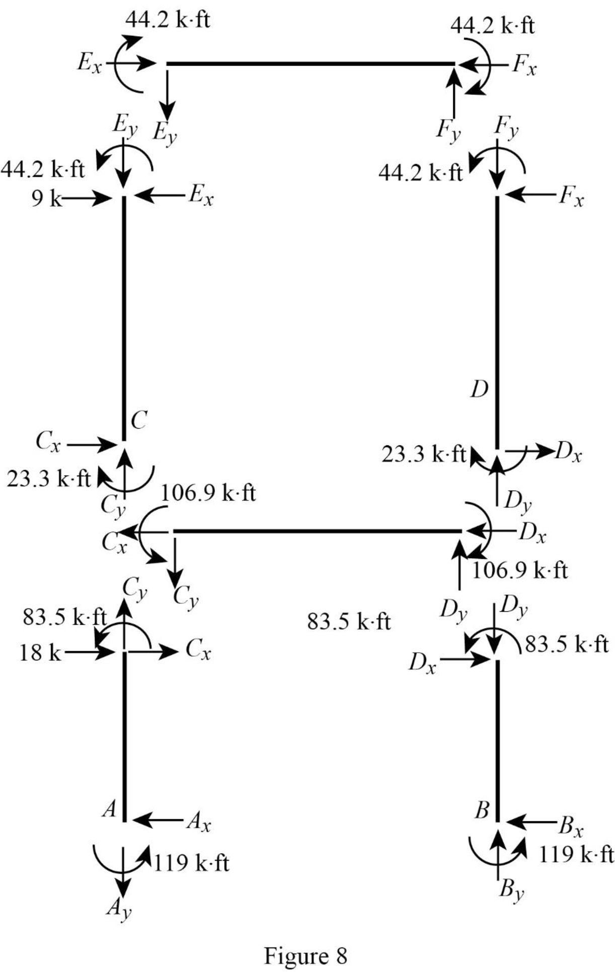
Consider member EF:
Calculate the vertical reaction at the joint E by taking moment about point F.
Calculate the vertical reaction at joint F by resolving the horizontal equilibrium.
Consider member CD:
Calculate the vertical reaction at the joint C by taking moment about point D.
Calculate the vertical reaction at joint D by resolving the horizontal equilibrium.
Calculate the reaction at joint A using the relation:
Calculate the reaction at joint B using the relation:
Consider member AC:
Calculate the horizontal reaction at the joint A by taking moment about point C.
Consider member BD:
Calculate the horizontal reaction at the joint B by taking moment about point D.
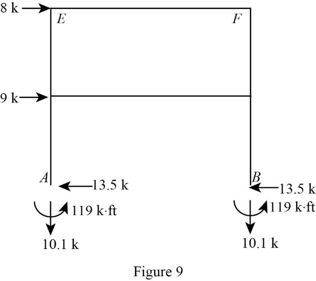
Show the reactions of the frame as in Figure 9.
Want to see more full solutions like this?
Chapter 16 Solutions
Structural Analysis (MindTap Course List)


- A tension member made of L4x4x1/2 is connected to gusset plate with welds. Using E70electrode and ½ inch weld size, design the balanced weld lengths.( Use AISC manual, LRFD units)arrow_forwardUsing the ultimate strength method, determine the maximum load, Pu, that the welded connectioncan carry. Weld size is ½ inch. The structural members are made of grade 50 steel. (Use AISC manual, LRFD units)arrow_forward21:52 | 2.3Kb.s ← CamScanner ۲۰۲۵-۰۴... هوا 8:05: ان 4.5G 443% به نام خدا تمرینات درس مکانیک سیالات سری دوم - حامد سرکرده 0.3m A 0.3m 0.6m روغن B $ 09 آب lm P=13.74kpa gage PA هوا 4.6m سال 0.3m 50mm Pc 13.72kpa gage EL = 50 EL = 30 ۱ در شکل رو به رو فشار در نقاط A, B, C,D بر حسب پاسکال چقدر است؟ فشار P چقدر است چگالی روغن ۰/۸ میباشد در داخل مخزن استوانه ای رو به رو که محتوی نفت به چگالی ۰/۸ میباشد مخزن استوانه ای آبی قرار گرفته است. مقدار P فشار نسبی در فشارسنج (A) و ارتفاع h چقدر است. ۴- لوله های A و B که حاوی آب در فشارهای ۲/۷۶ و ۱/۳۸ بار به ترتیب هستند اختلاف ارتفاع جیوه در مانومتر نشان داده شده در شکل چقدر است؟ چگالی جیوه ۱۳/۵۷ در نظر گرفته شود. Scanned with CamScannerarrow_forward
- h EL = 50 EL = 30arrow_forwardh EL = 50 EL = 30arrow_forwardCalculate the instantaneous deflections and the long term-term deflections after 15 years for the flat roofbeam shown below (simply supported). Use fy = 60,000 psi, fc′ = 4000 psi, and assume that the uniformdead load value shown does not include beam weight, and that none of the concentrated live loads aresustained. The concrete weight is 135 pcf. Investigate the deflection acceptability of the beam accordingto the ACI Code.arrow_forward
- a) Determine the global stiffness matrix of the beam shown in Figure below. Assume supports at 1 and 3 are rollers and the support at 2 is a pinned support. Indicate the degrees-of freedom in all the stiffness matrices. EI is constant. Use the values of w and L1 as 50 kN/m and 1.75m, respectively. Note, L2=3L1. b) Determine the rotations at all the nodes of the beam and reactions at the supports. Show all calculations. c) Draw the BMD of the beam on the compression side showing the salient values. What are the maximum bending moments of the beam? Draw the deflected shape of the beam.arrow_forward20 ft 8 #8 in 2-layers 18 in 30 inarrow_forwarda) Calculate the BMs (bending moments) at all the joints of the beam shown in Figure below using the moment distribution method. The beam is subjected to an UDL of w kN/m. L1= 0.4L. Assume the support at C is pinned, and A and B are roller supports. E = 200 GPa, I = 250x10^6 mm4. Use the values of w and L as 50kN/m and 5m respectively. b) Draw the shear force and bending diagrams for the entire beam. c) Calculate the BMs at all the joints of the same beam shown in Figure using the slope deflection method. d) Compare the values of BMs obtained using the two methods a) and c) and comment.arrow_forward
- The interior floor beam shown below at 3-year service life according to the ACI Code, supports partitions,etc. Maximum service load moments are 38 kip-ft dead load and 29 kip-ft live load. Assume that 50% ofthe live load is sustained. Use fc′ = 5000 psi, fy = 75,000 psi.a. Determine if the minimum deflection criteria from ACI is satisfied.b. Find the effective moment of inertia.c. Find the maximum instantaneous and long-term defecations.d. Check if the deflections are within ACI allowable limitsarrow_forwarda) For the truss shown in the figure below, determine the stiffness matrices of elements 2, 3 and 4 in the in the global co-ordinate system. Assume for each member A = 0.0015 m2 and E = 200 GPa. Indicate the degrees-of freedom in all the stiffness matrices. b) Determine the stiffness matrix of the whole truss in the global co-ordinate system. Clearly indicate the degrees-of freedom numbers in the stiffness matrix. c) Calculate all the nodal displacements and all the member forces of the truss.arrow_forwarda) Draw a 2D element and show the dofs (degrees of freedom). Draw all the 2D elements used in Strand7. Explain the differences between these elements in terms of the no. of nodes and interpolation/shape functions used. b) A 8 m x 8 m plate (in the xy plane) with 8 mm thickness, is fixed at all the edges and is loaded by a pressure loading of 4 kN/m2 in the downward (-z) direction. The plate is made of steel (E = 200 GPa, density = 7850 kg/m3). Explain the steps involved in setting up a Strand7 model for this problem. Your explanation should include how the given input data for this problem will be used in Strand7 modelling. Explain how you would determine the maximum deflection from the Strand7 output.arrow_forward
