
Concept explainers
Find the member end moments and reactions for the frames.
Answer to Problem 31P
The reaction at point A
The end moment at the member
Explanation of Solution
Fixed end moment:
Formula to calculate the relative stiffness for fixed support
Formula to calculate the fixed moment for point load with equal length are
Formula to calculate the fixed moment for point load with unequal length are
Formula to calculate the fixed moment for UDL is
Formula to calculate the fixed moment for UVL are
Formula to calculate the fixed moment for deflection is
Calculation:
Consider the elastic modulus E of the frame is constant.
Show the free body diagram of the entire frame as in Figure 1.
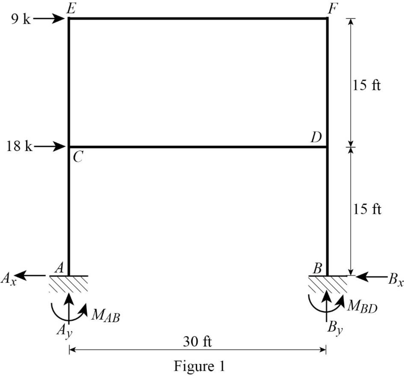
Refer Figure 1,
Calculate the relative stiffness
Calculate the relative stiffness
Calculate the distribution factor
Substitute
Calculate the distribution factor
Substitute
Calculate the distribution factor
Substitute
Check for sum of distribution factor as below:
Substitute
Hence, OK.
Calculate the distribution factor
Substitute
Calculate the distribution factor
Substitute
Check for sum of distribution factor as below:
Substitute
Hence, OK.
Calculate the distribution factor
Substitute
Calculate the distribution factor
Substitute
Check for sum of distribution factor as below:
Substitute
Hence, OK.
Calculate the distribution factor
Substitute
Calculate the distribution factor
Substitute
Calculate the distribution factor
Substitute
Check for sum of distribution factor as below:
Substitute
Hence, OK.
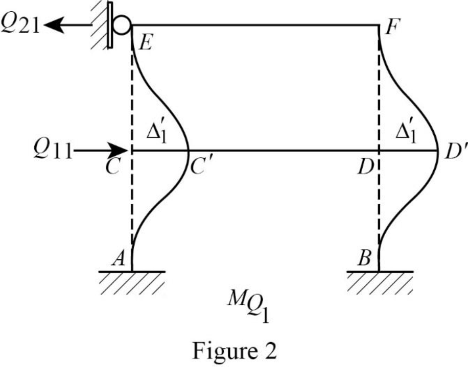
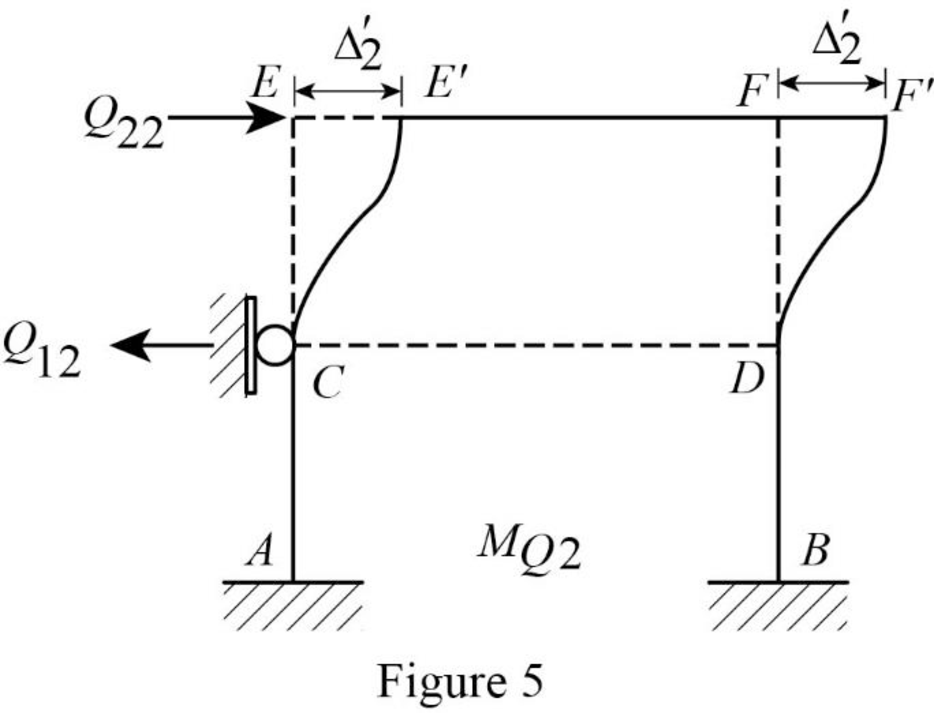
Show the translation
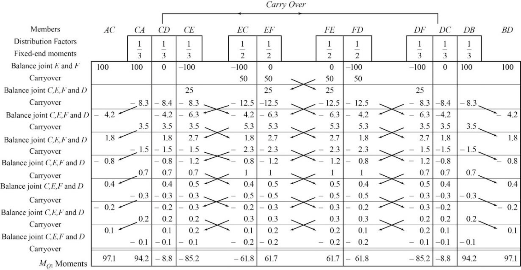
Write the expression to calculate the Fixed-end moment of the member.
Assume the Fixed-end moment of the members AC, CA, BD and DB as
Write the expression to calculate the Fixed-end moment of the member.
Assume the Fixed-end moment of the members CE, EC, DF and FD as
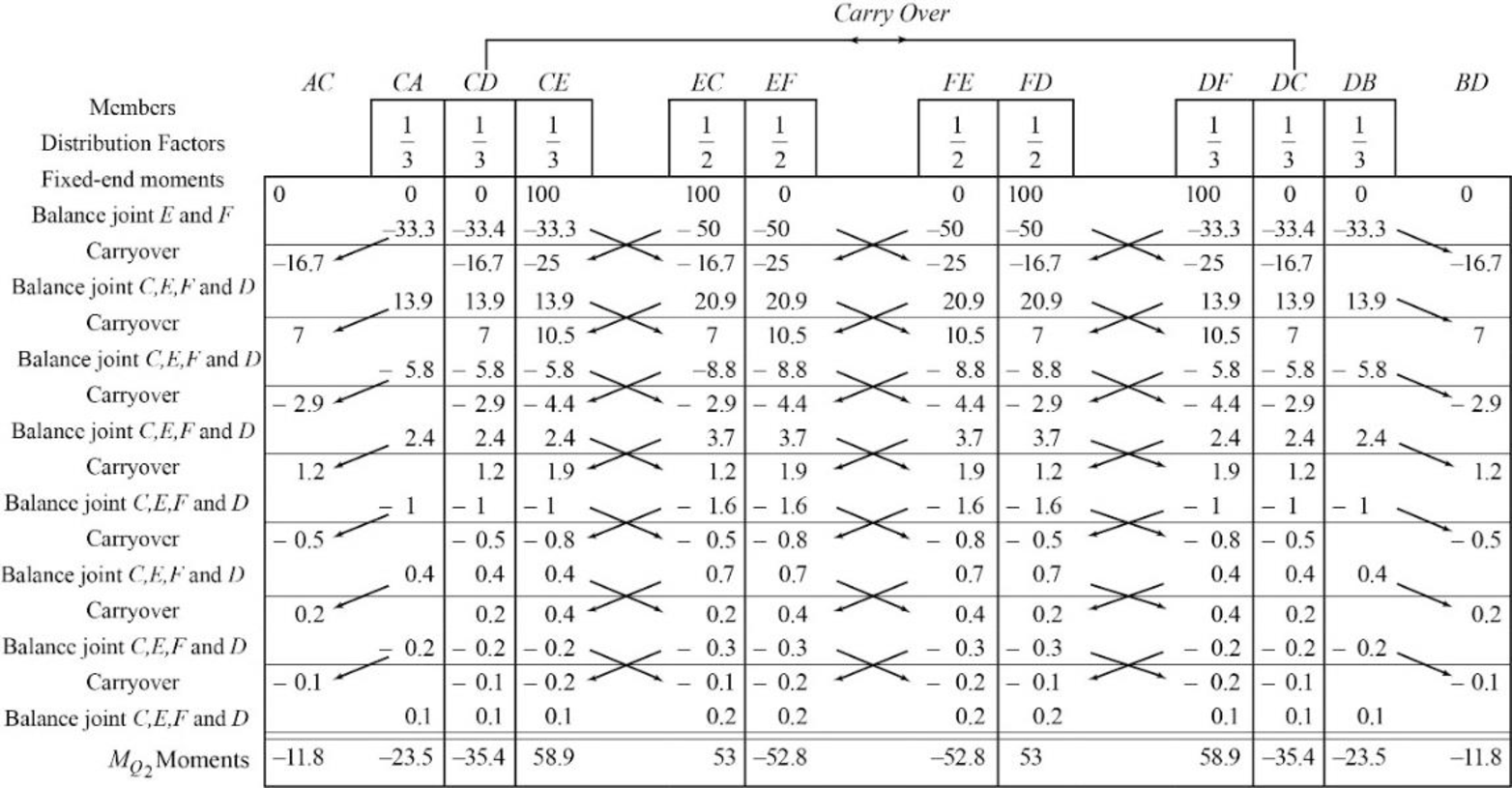
Show the calculation of
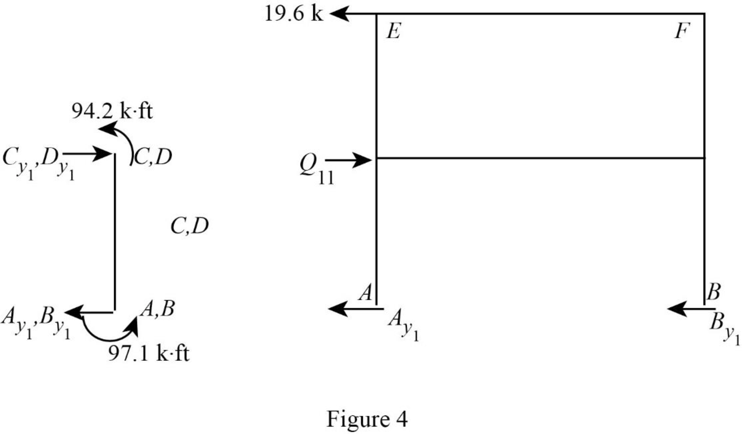
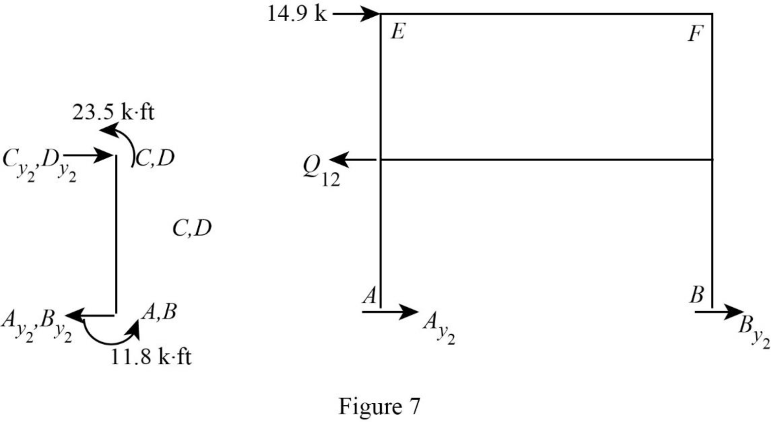
Show the free body diagram of the frame with unknown reaction
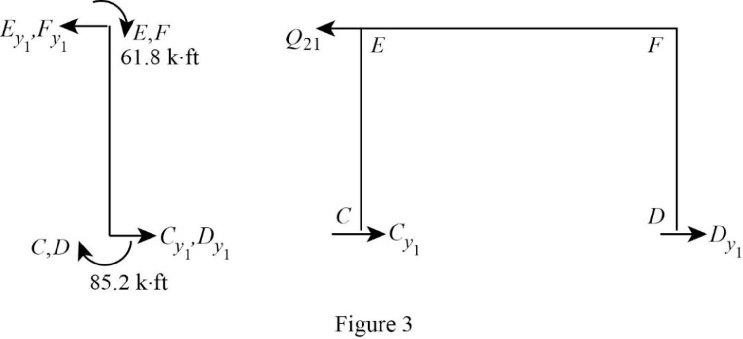
Consider member EC:
Calculate the horizontal reaction at the joint C by taking moment about point E.
Calculate the horizontal reaction at joint E by resolving the horizontal equilibrium.
Consider member FD:
Calculate the horizontal reaction at the joint D by taking moment about point F.
Calculate the horizontal reaction at joint F by resolving the horizontal equilibrium.
Calculate the reaction
Show the free body diagram of the frame with unknown reaction
Consider member AC:
Calculate the horizontal reaction at the joint A by taking moment about point C.
Calculate the horizontal reaction at joint C by resolving the horizontal equilibrium.
Consider member BD:
Calculate the horizontal reaction at the joint B by taking moment about point D.
Calculate the horizontal reaction at joint D by resolving the horizontal equilibrium.
Calculate the reaction
Show the translation
Write the expression to calculate the Fixed-end moment of the member.
Assume the Fixed-end moment of the members CE, EC, DF and FD as
Show the calculation of
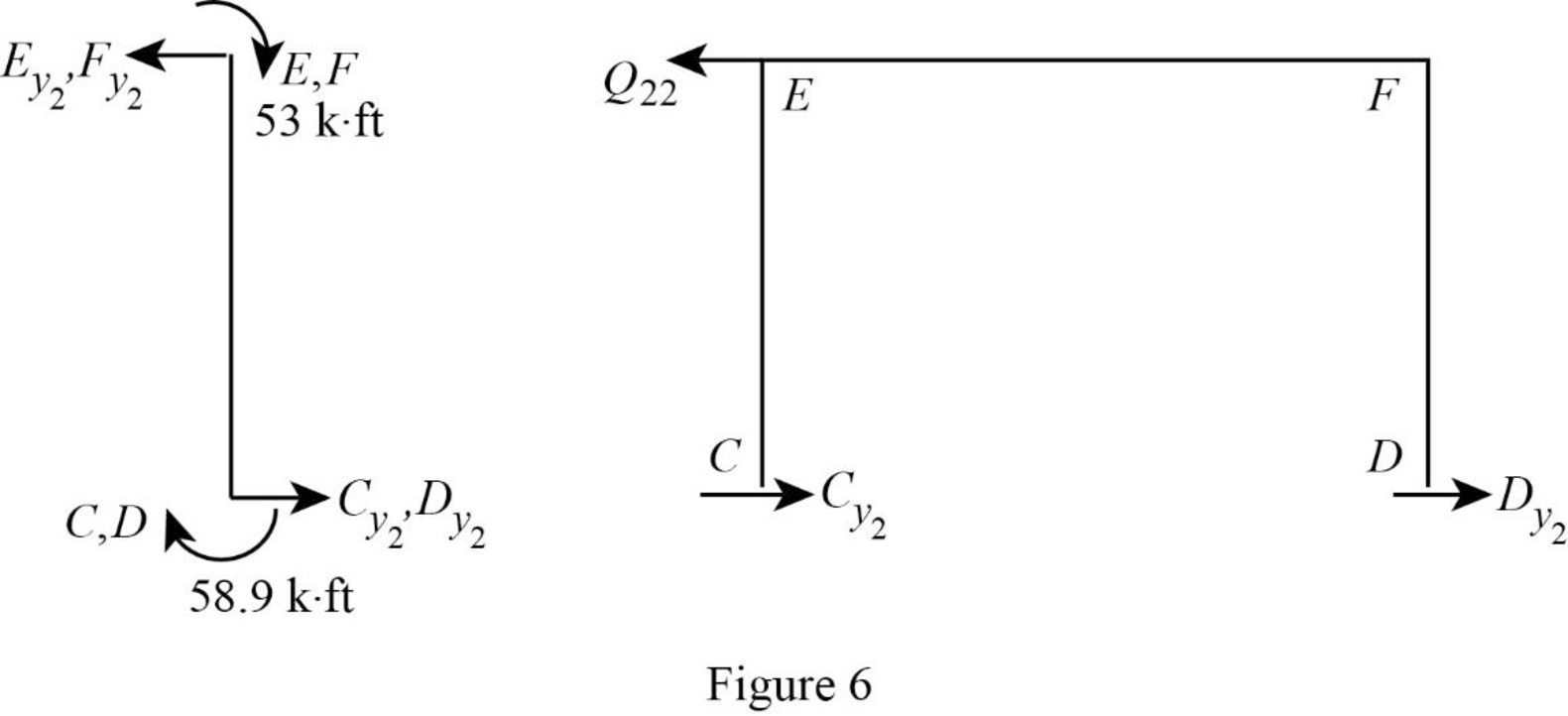
Show the free body diagram of the frame with unknown reaction
Consider member EC:
Calculate the horizontal reaction at the joint C by taking moment about point E.
Calculate the horizontal reaction at joint E by resolving the horizontal equilibrium.
Consider member FD:
Calculate the horizontal reaction at the joint D by taking moment about point F.
Calculate the horizontal reaction at joint F by resolving the horizontal equilibrium.
Calculate the reaction
Show the free body diagram of the frame with unknown reaction
Consider member AC:
Calculate the horizontal reaction at the joint A by taking moment about point C.
Calculate the horizontal reaction at joint C by resolving the horizontal equilibrium.
Consider member BD:
Calculate the horizontal reaction at the joint B by taking moment about point D.
Calculate the horizontal reaction at joint D by resolving the horizontal equilibrium.
Calculate the reaction
Write the equation by superimposing the horizontal forces at joints C,
Write the equation by superimposing the horizontal forces at joints E,
Calculate the value of
Calculate the actual member end moments of the member AC and BD:
Substitute
Calculate the actual member end moments of the member CA and DB:
Substitute
Calculate the actual member end moments of the member CD and DC:
Substitute
Calculate the actual member end moments of the member CE and DF:
Substitute
Calculate the actual member end moments of the member EC and FD:
Substitute
Calculate the actual member end moments of the member EC and FD:
Substitute
Show the section free body diagram of the member as in Figure 8.
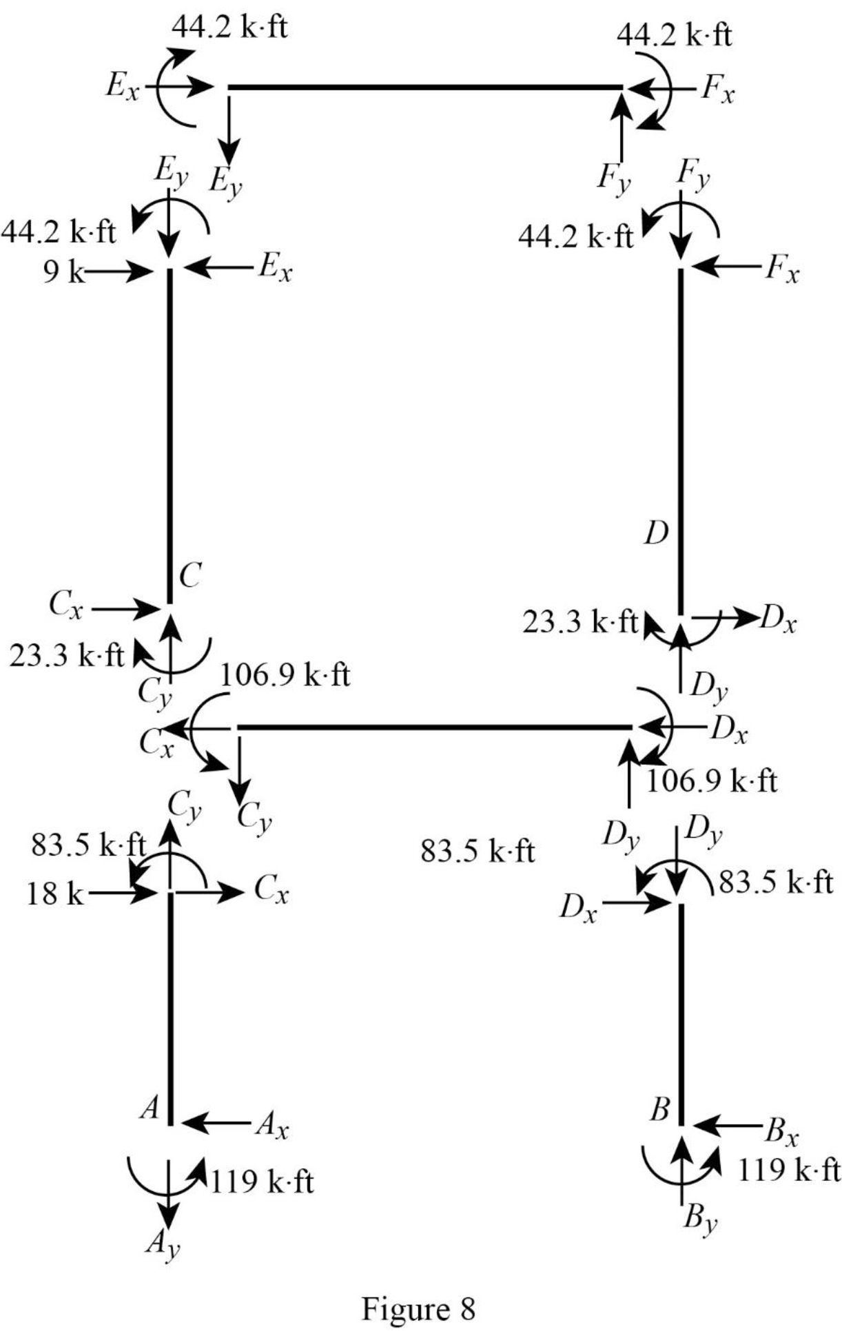
Consider member EF:
Calculate the vertical reaction at the joint E by taking moment about point F.
Calculate the vertical reaction at joint F by resolving the horizontal equilibrium.
Consider member CD:
Calculate the vertical reaction at the joint C by taking moment about point D.
Calculate the vertical reaction at joint D by resolving the horizontal equilibrium.
Calculate the reaction at joint A using the relation:
Calculate the reaction at joint B using the relation:
Consider member AC:
Calculate the horizontal reaction at the joint A by taking moment about point C.
Consider member BD:
Calculate the horizontal reaction at the joint B by taking moment about point D.
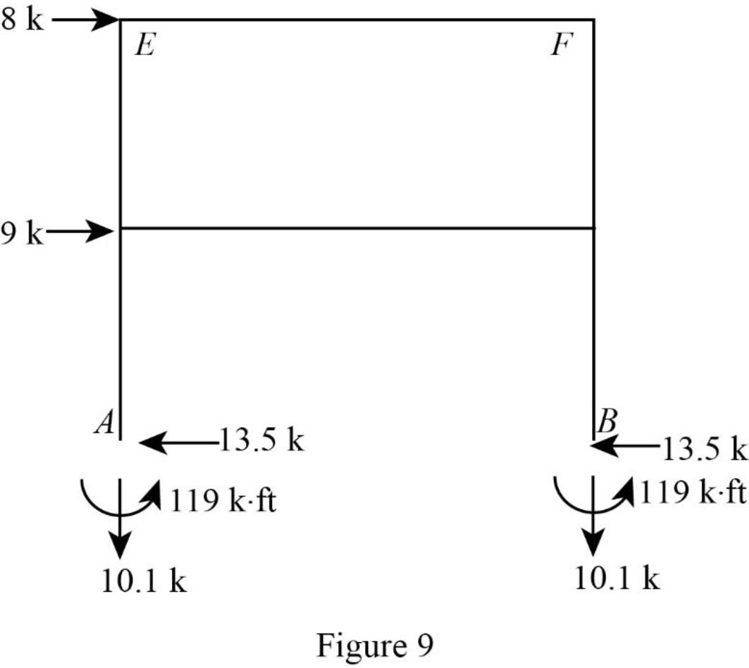
Show the reactions of the frame as in Figure 9.
Want to see more full solutions like this?
Chapter 16 Solutions
EBK STRUCTURAL ANALYSIS


- Draw the shear and the moment diagrams for each of the frames below. If the frame is statically indeterminate the reactions have been provided. Problem 1 (Assume pin connections at A, B and C). 30 kN 2 m 5 m 30 kN/m B 60 kN 2 m 2 m A 22 CO Carrow_forwardThis is an old exam practice question. The answer key says the answer is Pmax = 52.8kN but I am confused how they got that.arrow_forwardF12-45. Car A is traveling with a constant speed of 80 km/h due north, while car B is traveling with a constant speed of 100 km/h due east. Determine the velocity of car B relative to car A. pload Choose a File Question 5 VA - WB VBA V100 111413 + *12-164. The car travels along the circular curve of radius r = 100 ft with a constant speed of v = 30 ft/s. Determine the angular rate of rotation è of the radial liner and the magnitude of the car's acceleration. Probs. 12-163/164 pload Choose a File r = 400 ft 20 ptsarrow_forward
- P6.16 A compound shaft (Figure P6.16) consists of a titanium alloy [G= 6,200 ksi] tube (1) and a solid stainless steel [G= 11,500 ksi] shaft (2). Tube (1) has a length L₁ = 40 in., an outside diameter D₁ = 1.75 in., and a wall thickness t₁ = 0.125 in. Shaft (2) has a length 42 = 50 in. and a diameter d₂ = 1.25 in. If an external torque TB = 580 lb ft acts at pulley B in the direction shown, calculate the torque Tcrequired at pulley C so that the rotation angle of pulley Crelative to A is zero. B Te (2) TB (1) FIGURE P6.16arrow_forward7.43 Neglecting head losses, determine what horsepower the pump must deliver to produce the flow as shown. Here, the elevations at points A, B, C, and D are 124 ft, 161 ft, 110 ft, and 90 ft, respectively. The nozzle area is 0.10 ft². B Nozzle Water C Problem 7.43arrow_forwardA 1.8m x 1.8m footing is located at a depth of 1 m below the ground surface in a deep deposit of compacted sand (f'= 33 , f' = 28 , γ = 17.5 kN/m). Calculate the ultimate net bearing capacity considering several factors (e.g., shape, depth, and inclination) when the groundwater table is located (a) at 5 m below the footing base, (b) at the ground surface, (c) at the footing base, and (d) at 1.5 m below the footing base. Also, explain the effects of the groundwater levels in the bearing capacities of the footing with your own words. If the information is not given for the calculation, please assume it reasonably.arrow_forward
