Concept explainers
Find the member end moments and reactions for the frames.
Answer to Problem 30P
The reaction at point A
The end moment at the member
Explanation of Solution
Fixed end moment:
Formula to calculate the relative stiffness for fixed support
Formula to calculate the fixed moment for point load with equal length are
Formula to calculate the fixed moment for point load with unequal length are
Formula to calculate the fixed moment for UDL is
Formula to calculate the fixed moment for UVL are
Formula to calculate the fixed moment for deflection is
Calculation:
Consider the flexural rigidity EI of the frame is constant.
Show the free body diagram of the entire frame as in Figure 1.
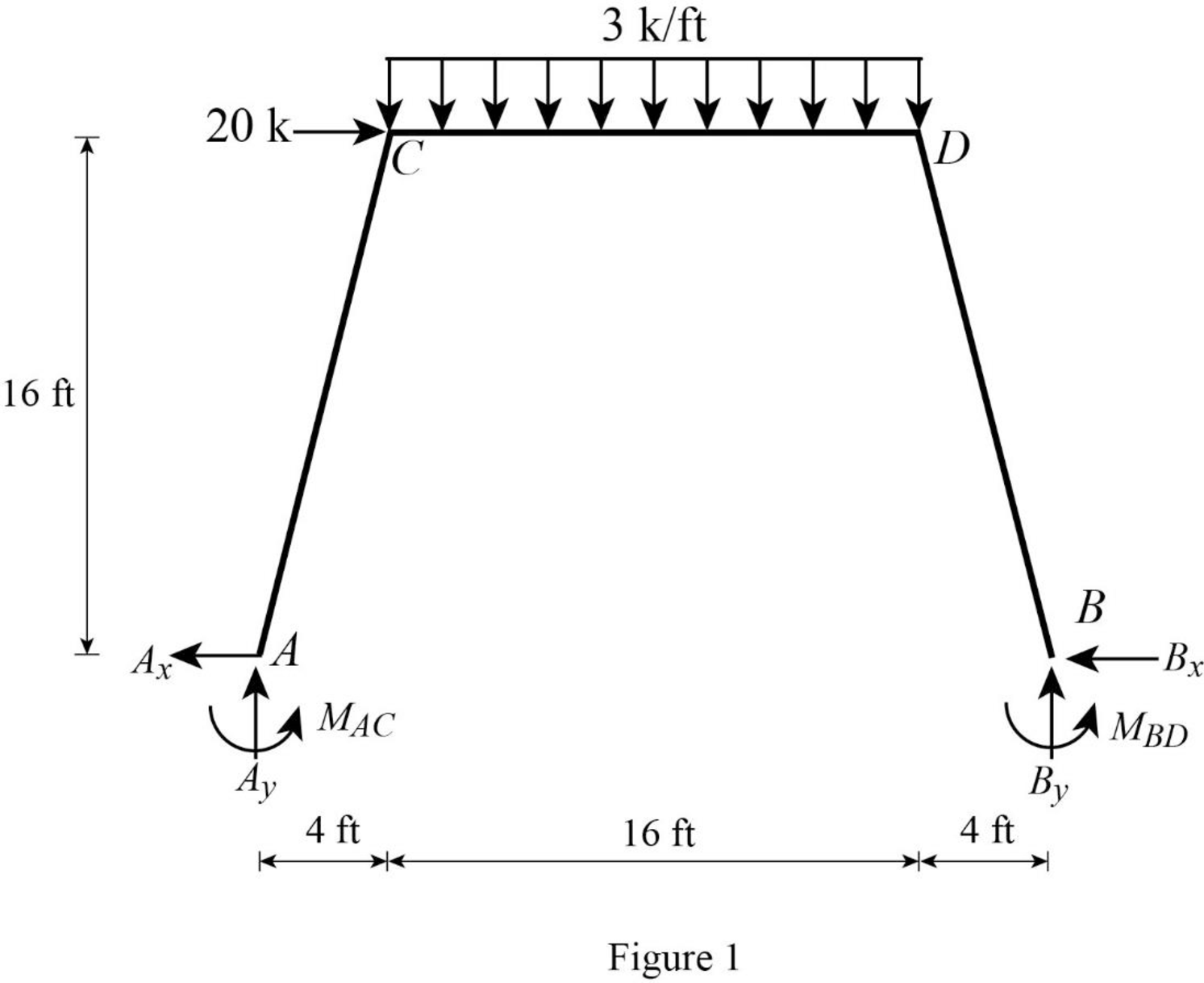
Refer Figure 1,
Calculate the length of the member AC and BD:
Calculate the relative stiffness
Calculate the relative stiffness
Calculate the relative stiffness
Calculate the distribution factor
Substitute
Calculate the distribution factor
Substitute
Check for sum of distribution factor as below:
Substitute 0.492 for
Hence, OK.
Calculate the distribution factor
Substitute
Calculate the distribution factor
Substitute
Check for sum of distribution factor as below:
Substitute 0.508 for
Hence, OK.
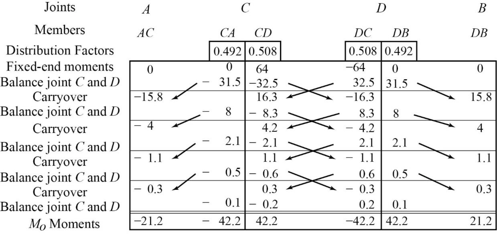
Calculate the fixed end moment for AC and CA.
Calculate the fixed end moment for CD.
Calculate the fixed end moment for DC.
Calculate the fixed end moment for DB and BD.
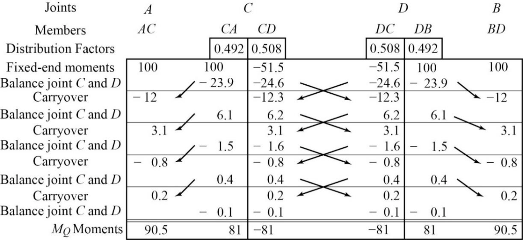
Show the calculation of
Show the arbitrary translation as in Figure 2.
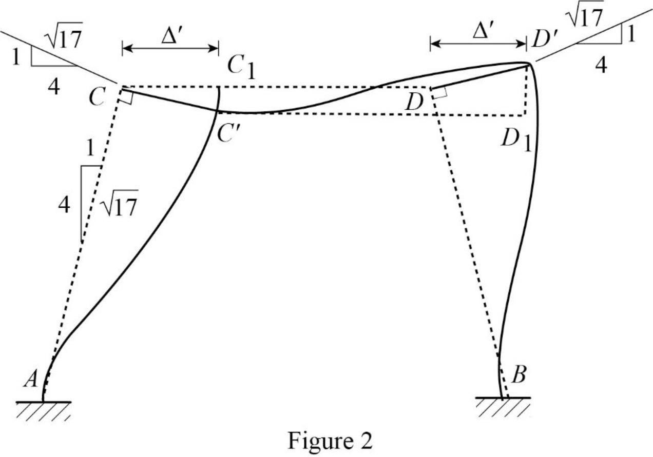
Calculate the relative translation
Calculate the relative translation
Calculate the relative translation
Calculate the fixed end moment for AC and CA.
Substitute
Calculate the fixed end moment for CD and DC.
Substitute
Calculate the fixed end moment for BD and DB.
Substitute
Assume the Fixed-end moment at AC and CA as
Calculate the value of
Substitute
Calculate the fixed end moment of CD and DC.
Substitute 4,395.7 for
Calculate the fixed end moment of BD and DB.
Substitute 4,395.7 for
Show the calculation of
Show the free body diagram of the member AC, CD and DB for side-sway permitted as in Figure 3.
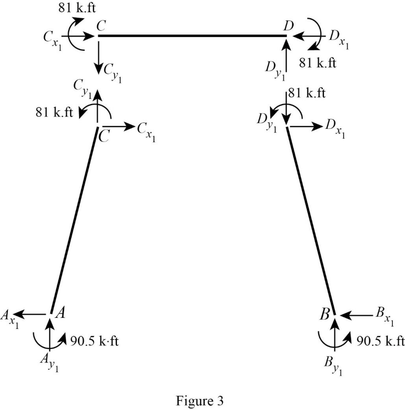
Consider member CD:
Calculate the vertical reaction at the joint C by taking moment about point D.
Calculate the vertical reaction at joint D by resolving the horizontal equilibrium.
Consider member AC
Calculate vertical reaction at joint A using the relation:
Calculate horizontal reaction at joint A by taking moment about point C
Calculate the horizontal reaction at joint C by resolving the horizontal equilibrium.
Consider member DB:
Calculate vertical reaction at joint B using the relation:
Calculate horizontal reaction at joint B by taking moment about point D
Calculate the horizontal reaction at joint D by resolving the horizontal equilibrium.
Show the unknown load Q as in Figure 4.
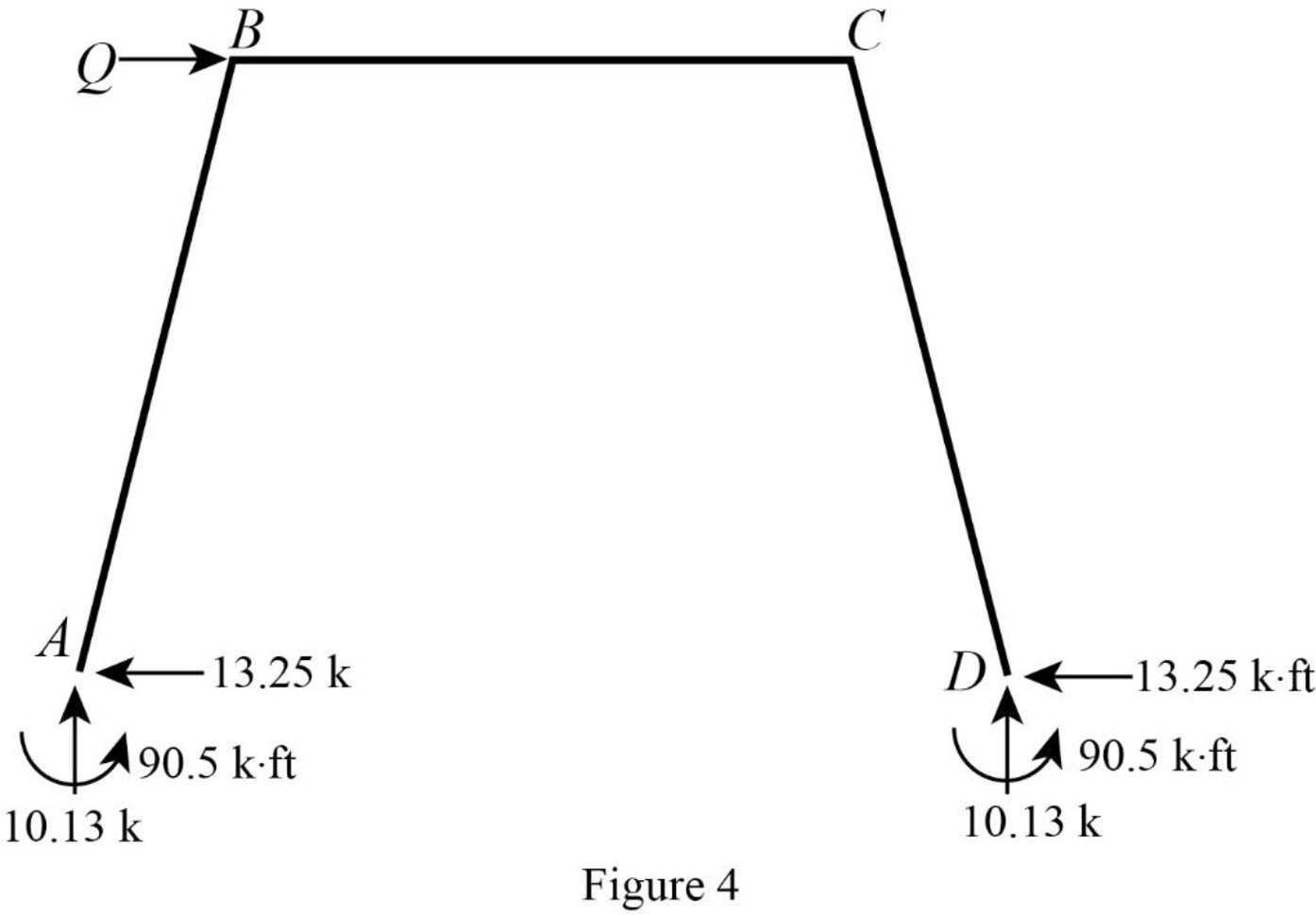
Calculate the reaction R using the relation:
Calculate the actual member end moments of the member AC:
Substitute
Calculate the actual member end moments of the member CA:
Substitute
Calculate the actual member end moments of the member CD:
Substitute
Calculate the actual member end moments of the member DC:
Substitute
Calculate the actual member end moments of the member DB:
Substitute
Calculate the actual member end moments of the member BD:
Substitute
Show the section free body diagram of the member AC, CD and DB as in Figure 5.
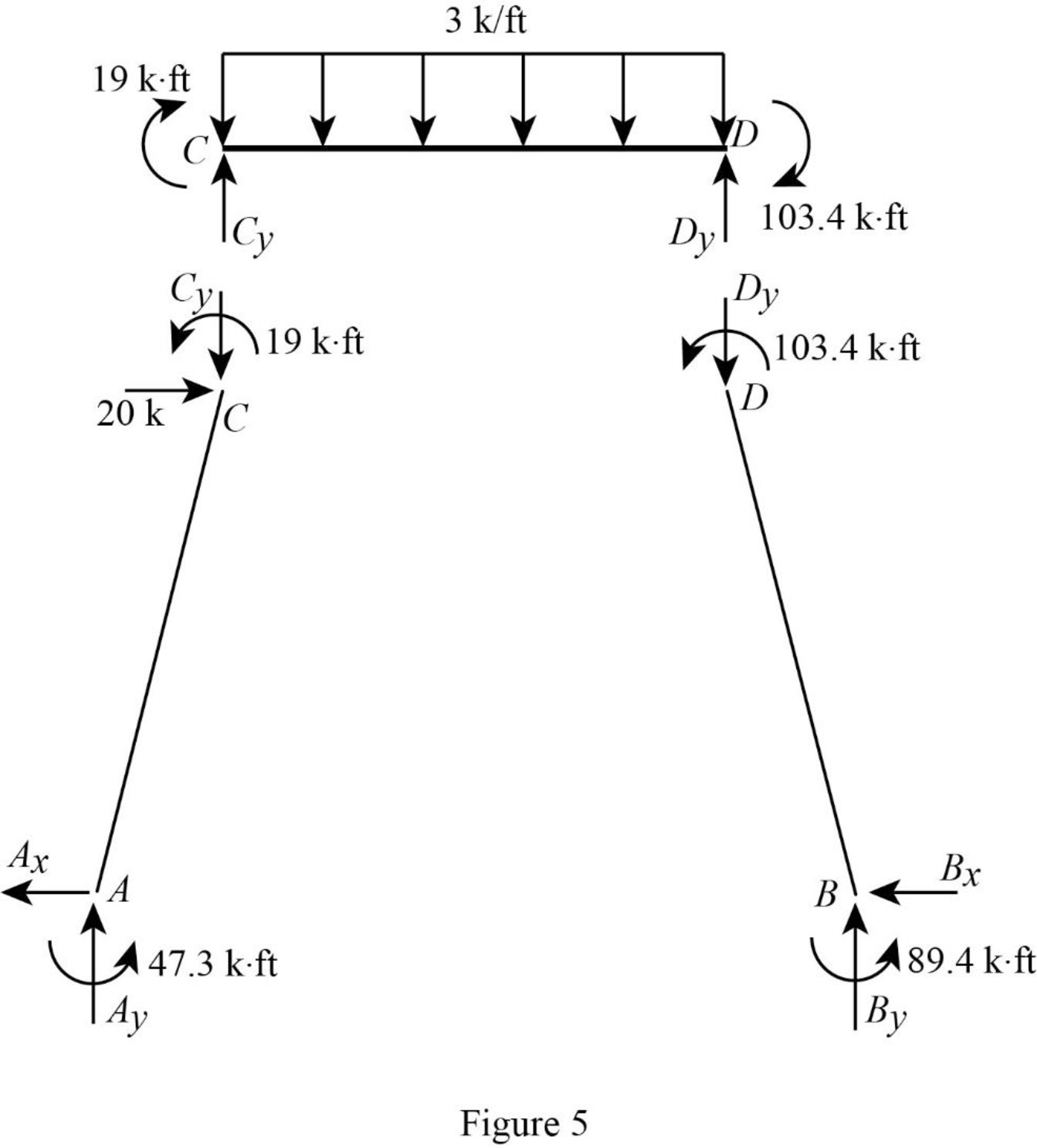
Consider the member CD.
Calculate the vertical reaction at the joint D by taking moment about point C.
Calculate the vertical reaction at joint C by resolving the vertical equilibrium.
Consider the member AC.
Calculate the vertical reaction at joint A by resolving the vertical equilibrium.
Calculate the horizontal reaction at the joint A by taking moment about point C.
Consider the member BD.
Calculate the vertical reaction at joint B by resolving the vertical equilibrium.
Consider the entire frame.
Calculate the horizontal reaction at the joint B by considering the horizontal equilibrium.
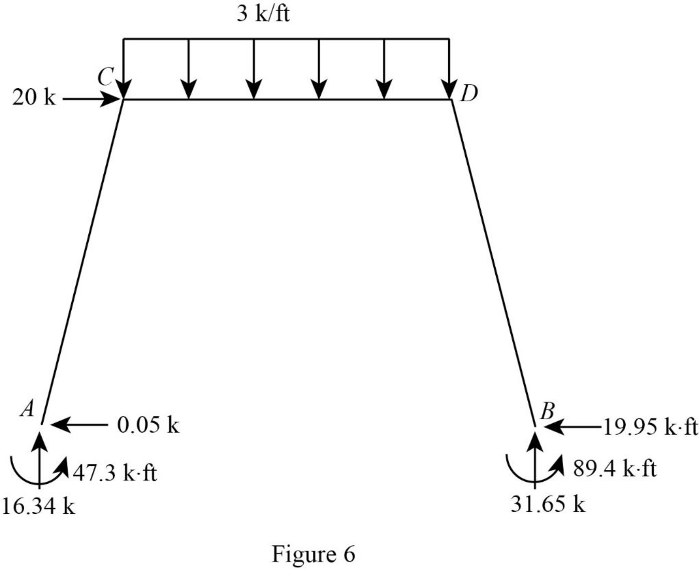
Show the reactions of the frame as in Figure 6.
Want to see more full solutions like this?
Chapter 16 Solutions
Structural Analysis, Si Edition


- Miniatry of Higher scent Research University of Ke Faculty of Engineering Cell Engineering Department 2024-2025 Mid Exam-1 st Attempt Time Date: 17/04/2025 Notes: Answer all questions. Not all figures are to scale. Assume any values if you need them. Q1/ A farm with dimensions and slopes (50 Marks) = shown in the figure below. If you asked to design a border irrigation system and if you know that Net depth of irrigation - 96mm .Manning coefficient = 0.15, Time of work in the farm is 6 hours/day. Design consumption use of water from the crop (ET) 16 mm/day, Width of the agricultural machine equal to 2.5m, Equation of infiltration - D= 12-05 and Efficiency of irrigation= 60%. You can neglect the recession lag time. Find the width and number of the borders, Irrigation interval and time required to irrigate the whole farm, Depth of flow in the inlet of border Number of borders that irrigated in one day and The neglected recession lag time Slope of irrigation % Maximum border width 0-0.1 30…arrow_forwardPLease make sure to show all work and all steps for the image find the magnitude and stressesarrow_forwardShowing all work and steps find the magnituded and stress ,arrow_forward
- What is the value of the influence line for the reaction at support A for the beam shown at 5 m to the right of A? Select the reaction at support B to be the redundant. a. 0 kN b. -0.167 kN c. 0.425 kN d. 1.0 kNarrow_forwardDetermine the force in member AB of the truss shown due to a temperature drop of 25°C in Members AB, BC, and CD and a temperature increase of 60°C in member EF. Use the method of consistent deformations. a. 37.34 k b. 0 k c. 28 k d. 46.67 karrow_forwardWhat is the approximate axial force in girder EF of the frame shown? Use the portal method. a. 32 kN b. 60 kN c. 12 kN d. 20kNarrow_forward
- Determine the vertical reaction at C for the beam shown and support settlements of 1" at B and ¼" at C. a. 27.0 k b. 28.3 k c. 43.7 k d. 21.0 karrow_forwardWhat is the horizontal reaction component at D for the frame shown? a. 75.00 kN b. 91.67 kN c. 70.31 kN d. 4.69 kNarrow_forwardFind the vertical reaction at D for the frame shown and a settlement of 50 mm at support D. a. 80.7 kN b. 112.5 kN c. 144.3 kN d. 6.51 kNarrow_forward
- Determine if the W14x 22 beam will safely support a loading of w= 1.5 kip/ft. Theallowable bending stress is oallow = 22 ksi and the allowable shear stress is Tallow = 12 ksi.arrow_forwardWhat is the fixed end moment FEMAB for the beam shown with a settlement of 1.2 in. at support B? a. -102.7 ft-k b. -95.2 ft-k c. -307.7 ft-k d. 279.8 ft-karrow_forwardSuggest an optimum footing size and shape (minimum area footing), if the vertical loading (includingthe weight of the footing) is 40 kips, and the soil has the following characteristics: c=200 psf, φ=370,and γ=120.0 lb/ft 3. Constraints of the solution are: the maximum dimension of any side of thefooting is 10 ft, and the depth of embedment is between 2 and 4 ft.arrow_forward
