Concept explainers
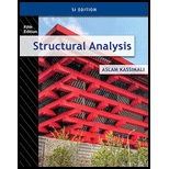
Find the member end moments and reactions for the frames.
Answer to Problem 29P
The reaction at point A
The end moment at the member
Explanation of Solution
Fixed end moment:
Formula to calculate the relative stiffness for fixed support
Formula to calculate the fixed moment for point load with equal length are
Formula to calculate the fixed moment for point load with unequal length are
Formula to calculate the fixed moment for UDL is
Formula to calculate the fixed moment for UVL are
Formula to calculate the fixed moment for deflection is
Calculation:
Consider the flexural rigidity EI of the frame is constant.
Show the free body diagram of the entire frame as in Figure 1.
Refer Figure 1,
Calculate the length of the member AC:
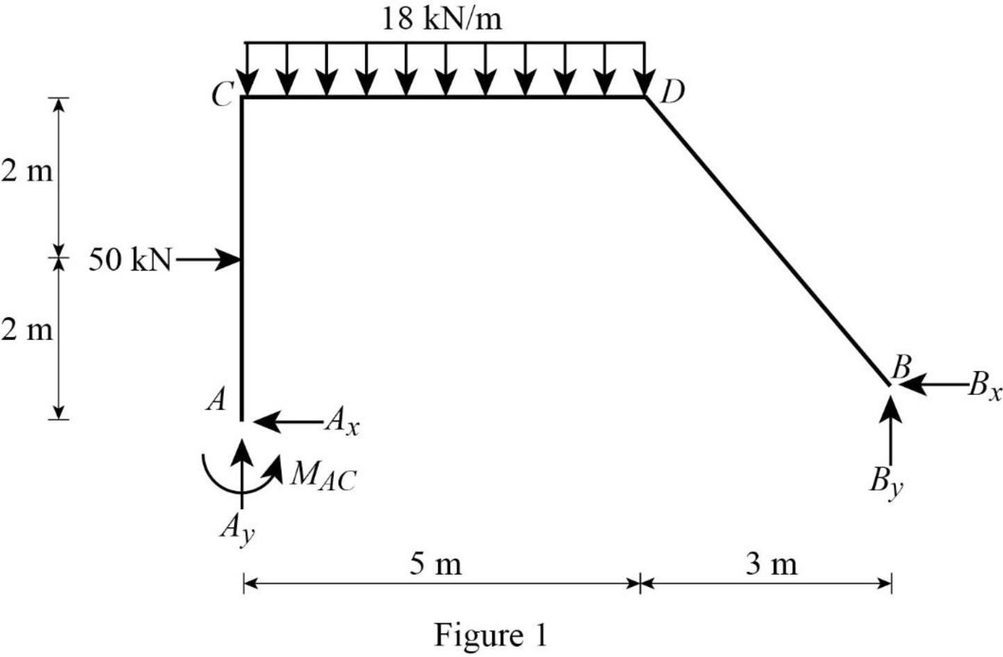
Calculate the relative stiffness
Calculate the relative stiffness
Calculate the relative stiffness
Calculate the relative stiffness
Calculate the distribution factor
Substitute
Calculate the distribution factor
Substitute
Check for sum of distribution factor as below:
Substitute 0.556 for
Hence, OK.
Calculate the distribution factor
Substitute
Calculate the distribution factor
Substitute
Check for sum of distribution factor as below:
Substitute 0.571 for
Hence, OK.
Calculate the fixed end moment for AC.
Calculate the fixed end moment for CA.
Calculate the fixed end moment for CD.
Calculate the fixed end moment for DC.
Calculate the fixed end moment for DB and BD.
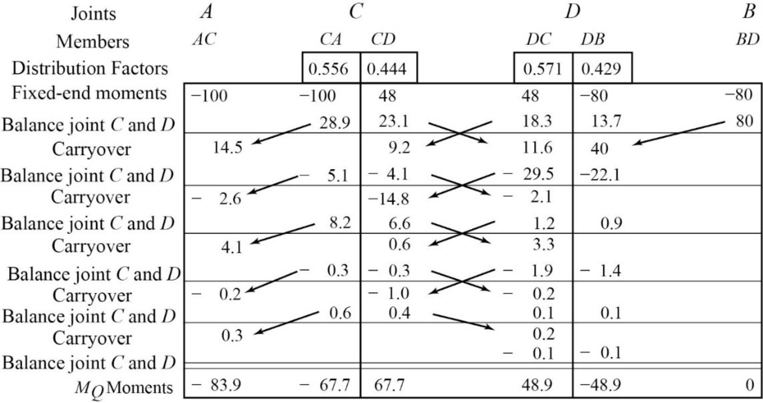
Show the calculation of
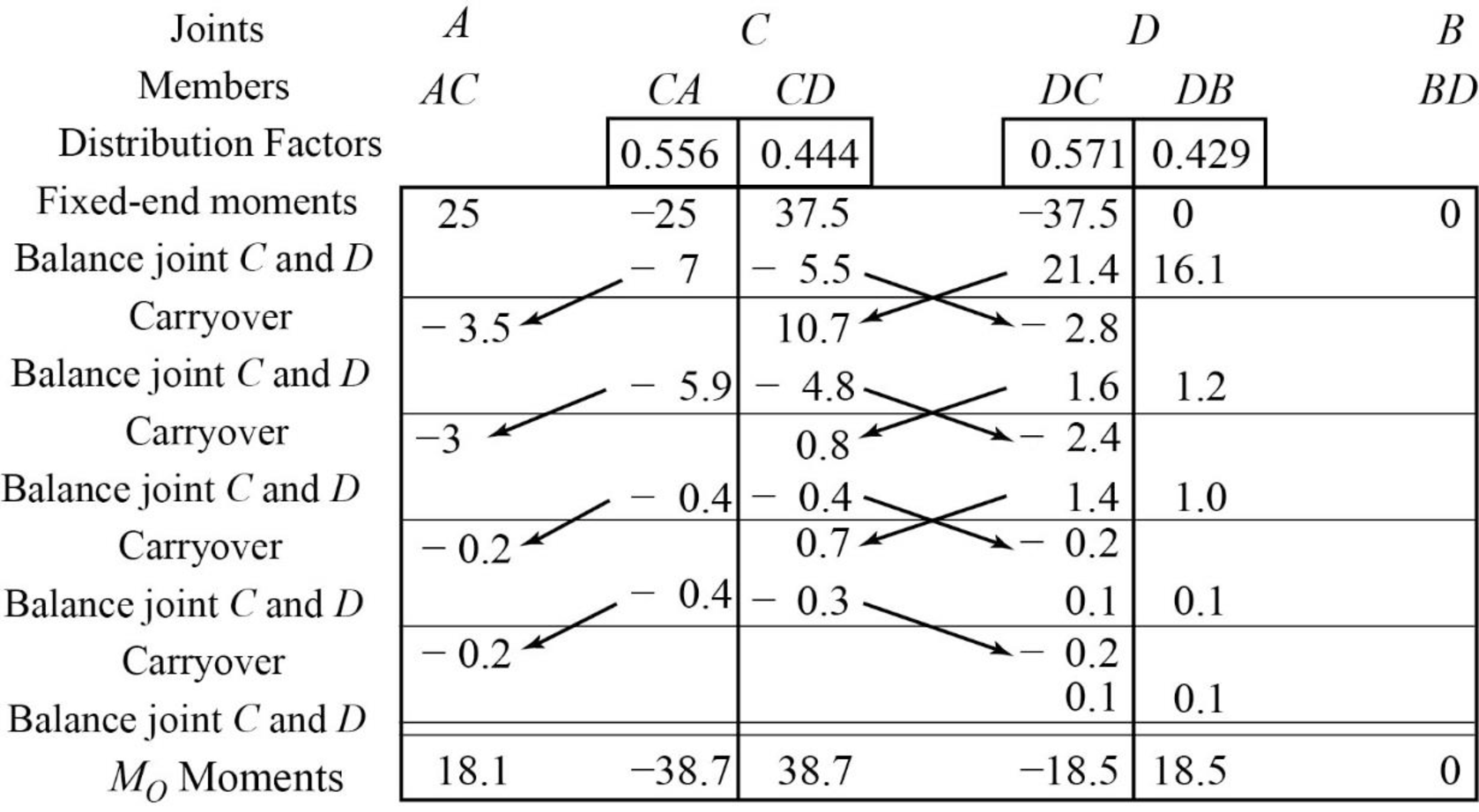
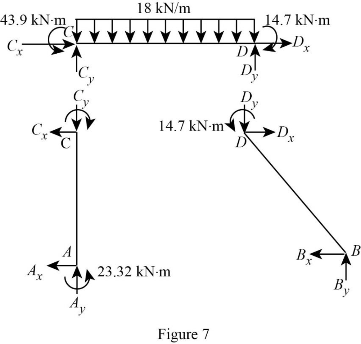
Show the free body diagram of the member AC, CD and DB for side-sway prevented as in Figure 2.
Consider member CD:
Calculate the vertical reaction at the joint C by taking moment about point D.
Calculate the vertical reaction at joint D by resolving the horizontal equilibrium.
Consider member AC
Calculate vertical reaction at joint A using the relation:
Calculate horizontal reaction at joint A by taking moment about point C.
Calculate the horizontal reaction at joint C by resolving the horizontal equilibrium.
Consider member DB:
Calculate vertical reaction at joint B:
Calculate horizontal reaction at joint B by taking moment about point D.
Calculate the horizontal reaction at joint D by resolving the horizontal equilibrium.
Show the unknown load R as in Figure 3.
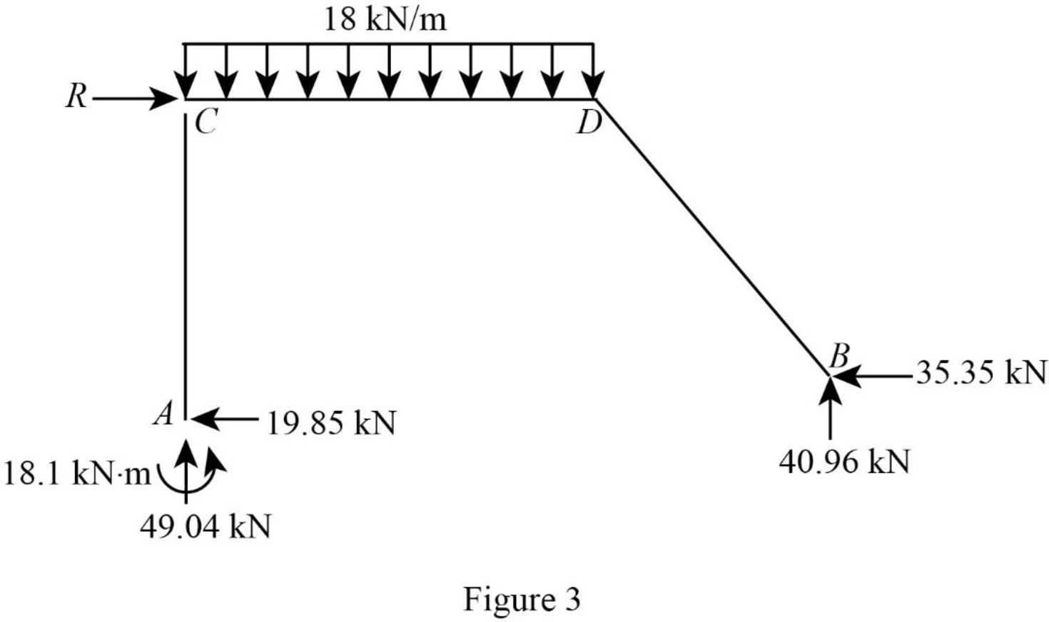
Calculate the reaction R:
Show the arbitrary translation as in Figure 4.
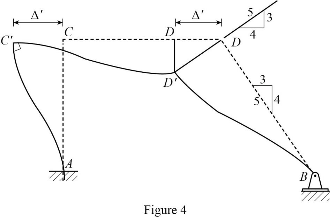
Calculate the relative translation
Calculate the relative translation
Calculate the relative translation
Calculate the fixed end moment for AC and CA.
Substitute
Calculate the fixed end moment for CD and DC.
Substitute
Calculate the fixed end moment for BD and DB.
Substitute
Assume the Fixed-end moment at AC, and CA as
Calculate the value of
Substitute
Calculate the fixed end moment of CD and DC.
Substitute 266.7 for
Calculate the fixed end moment of BD and DB.
Substitute 266.7 for
Show the calculation of
Show the free body diagram of the member AC, CD and DB for side-sway permitted as in Figure 5.
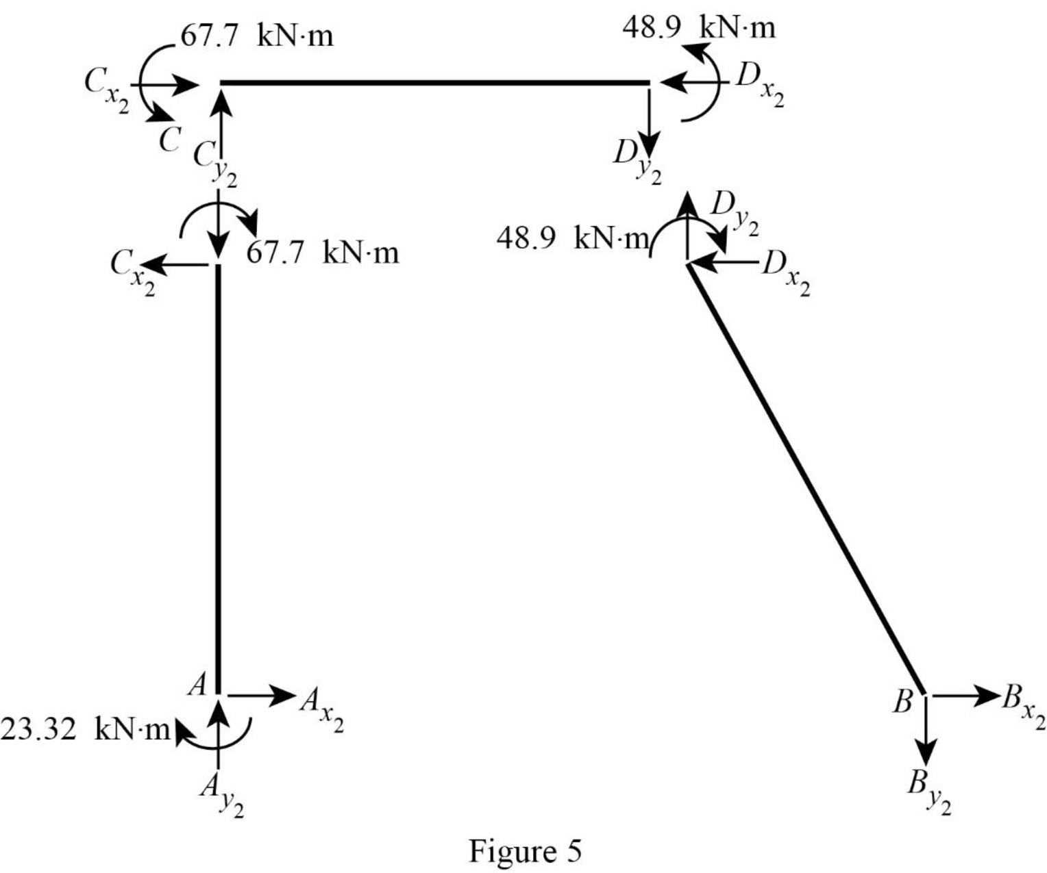
Consider member CD:
Calculate the vertical reaction at the joint C by taking moment about point D.
Calculate the vertical reaction at joint D by resolving the horizontal equilibrium.
Consider member AC
Calculate vertical reaction at joint A using the relation:
Calculate horizontal reaction at joint A by taking moment about point C
Calculate the horizontal reaction at joint C by resolving the horizontal equilibrium.
Consider member DB:
Calculate vertical reaction at joint B:
Calculate horizontal reaction at joint B by taking moment about point D
Calculate the horizontal reaction at joint D by resolving the horizontal equilibrium.
Show the unknown load Q as in Figure 6.
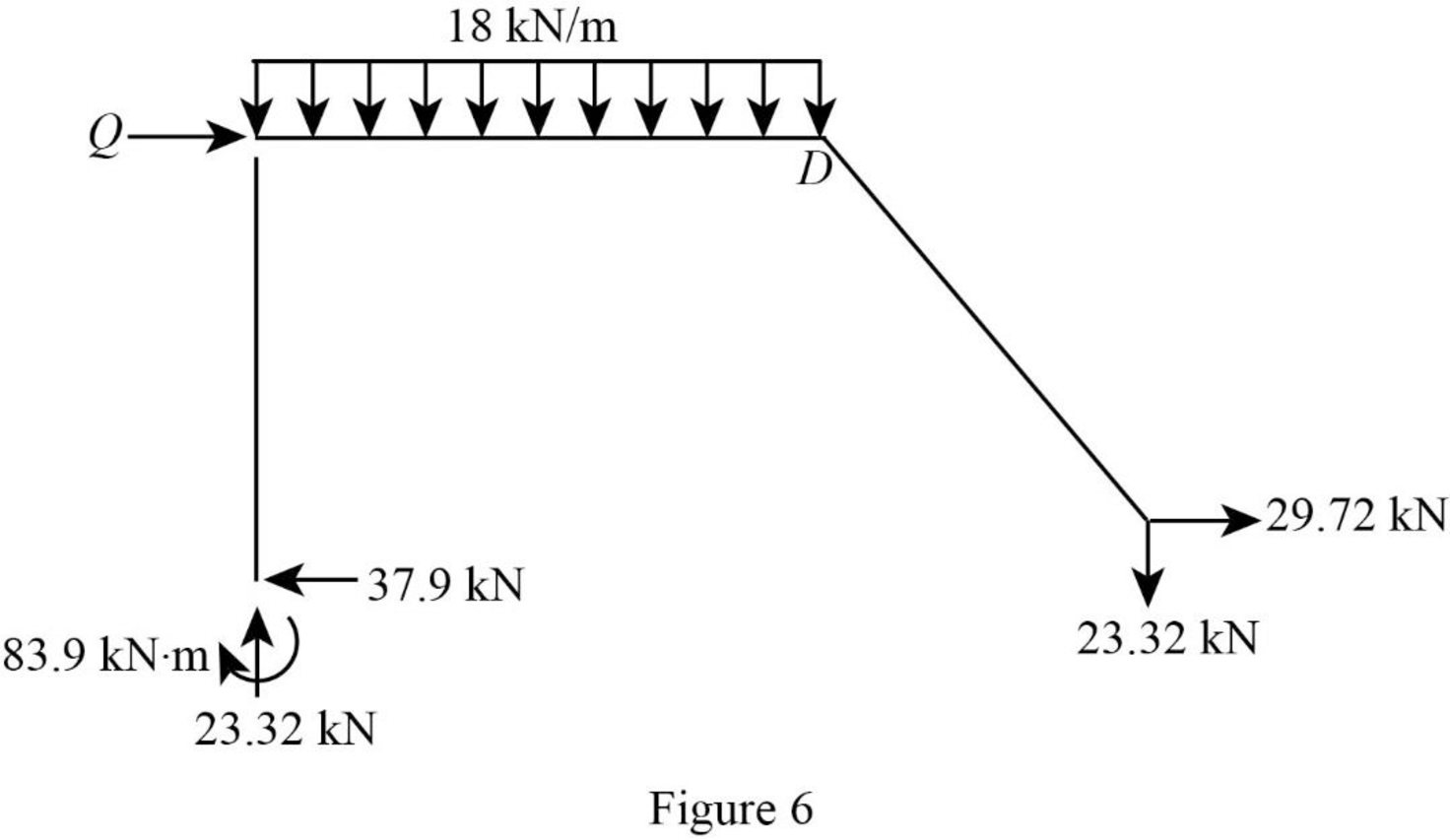
Calculate the reaction Q:
Calculate the actual member end moments of the member AC:
Substitute
Calculate the actual member end moments of the member CA:
Substitute
Calculate the actual member end moments of the member CD:
Substitute
Calculate the actual member end moments of the member DC:
Substitute
Calculate the actual member end moments of the member DB:
Substitute
Calculate the actual member end moments of the member BD:
Substitute
Show the section free body diagram of the member AC, CD, and DB as in Figure 5.
Consider member CD:
Calculate the vertical reaction at the joint C by taking moment about point D.
Calculate the vertical reaction at joint D by resolving the horizontal equilibrium.
Consider member AC
Calculate vertical reaction at joint A:
Calculate horizontal reaction at joint A by taking moment about point C.
Calculate the horizontal reaction at joint C by resolving the horizontal equilibrium.
Consider member DB:
Calculate vertical reaction at joint B using the relation:
Calculate horizontal reaction at joint B.
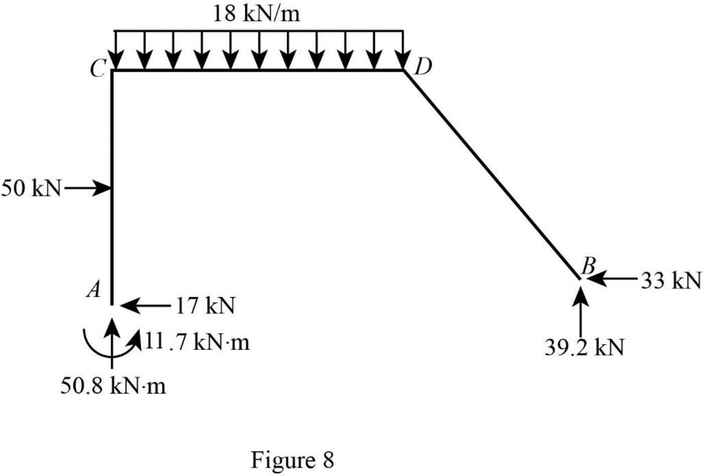
Show the reactions of the frame as in Figure 8.
Want to see more full solutions like this?
Chapter 16 Solutions
Structural Analysis, Si Edition


- I need detailed help solving this exercise from homework of Engineering Mathematics II.I do not really understand how to do, please do it step by step, not that long but clear. Thank you!P.S.: Please do not use AI, thanks!arrow_forwardI need detailed help solving this exercise from homework of Engineering Mathematics II.I do not really understand how to do, please do it step by step, not that long but clear. Thank you!P.S.: Please do not use AI, thanks!arrow_forwardI need detailed help solving this exercise from homework of Engineering Mathematics II.I do not really understand how to do, please do it step by step, not that long but clear. Thank you!P.S.: Please do not use AI, thanks!arrow_forward
- I need detailed help solving this exercise from homework of Engineering Mathematics II.I do not really understand how to do, please do it step by step, not that long but clear. Thank you!P.S.: Please do not use AI, thanks!arrow_forwardI need detailed help solving this exercise from homework of Engineering Mathematics II.I do not really understand how to do, please do it step by step, not that long but clear. Thank you!P.S.: Please do not use AI, thanks!arrow_forwardB1.For the truss below, take P₁ = 4 kip and P₂ = 3 kip: a. Determine all member forces. Hint: first find zero-force members (16 pts). b. Use a section cut to verify your answers for members JI, BI, and BC (4 Pts) В 18 ft 6 ft H B 6 ft C 8 ft D p81 8 ft E 8 ft 6 ft F6ftarrow_forward
- Q13: The line CD, C(xc, 6), D(6,yd), the point D is on the right of point C, the value of horizontal effect H(3,0) is on the right of point C, the vertical effect V(0, -2) right of H. the distance between projection of the points H, V is 5cm, Find: 1- The value of xc and yd. 2- The distance between projections of the points C, D. 3- The true length (T.L.) of CD. 4- The angles a and ẞ. 5- A point F in the middle of line CD, find F (xf, yf).arrow_forwardQ9: The straight line AB of true length (8) cm, having the following data: A (5, ya) & B (xb, yb), the point B is on the left of point A, the inclination of the line to the horizontal plane (H.P) is 30° (a) it Horizontal trace H (-3, 0), and point H is on the left of point A with distance (16) cm. Draw the Plan & Elevation of the line AB and determine the following: 1. The missed coordinates: ya, xb, yb. 2. The coordinates of the vertical trace (V). 3. The inclination of the line to the vertical plane (V.P) (B). 4. The distance between projections of the points A and Barrow_forwardQ12: The straight line AB, having the following data: the distance between projections of the points A and B is 8 cm, and A (2.5, 0) & B (0, 6), the point B is on the left of point A. Draw the Plan & Elevation of the line AB and determine the following: 1. The true length T.L of the line AB. 2. The coordinate of Vertical trace V and Horizontal trace H. 3. The inclination of the line to the V.P and H.P. 4. A point E in the middle of the line AB, find E (xe,ye).arrow_forward
- Deformation of a retaining wall is assumed to be as presented in the figure below. Determine:a) variation of the active and passive pressures on the wall for the presented deformation b) magnitude of the total horizontal force on the right side of the wall.arrow_forward2. a) Consider a cable used for aerial tramway (see figure a). The span is 400 m. The unstretched length of the cable is 402 m. Its mass per unit length is 10kg. The elasticity EA = 10 N. Find the horizontal load on the two ends and the sag d. Determine if the small sag condition is satisfied. b) When a cable car whose mass is 500kg is hung below the cable at a horizontal distance of 100 m from the left end, find the horizontal load on the ends. C) As the car goes along the cable, at which position you will see maximum horizontal load on the two ends?arrow_forwardTwo square surface footings are placed 20 feet apart. Calculate ultimate settlements beneath footing I and at the centerline of the two footings.arrow_forward
