
Concept explainers
Find the member end moments and reactions for the frames.
Answer to Problem 29P
The reaction at point A
The end moment at the member
Explanation of Solution
Fixed end moment:
Formula to calculate the relative stiffness for fixed support
Formula to calculate the fixed moment for point load with equal length are
Formula to calculate the fixed moment for point load with unequal length are
Formula to calculate the fixed moment for UDL is
Formula to calculate the fixed moment for UVL are
Formula to calculate the fixed moment for deflection is
Calculation:
Consider the flexural rigidity EI of the frame is constant.
Show the free body diagram of the entire frame as in Figure 1.
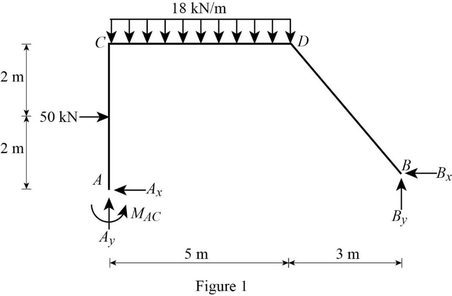
Refer Figure 1,
Calculate the length of the member AC:
Calculate the relative stiffness
Calculate the relative stiffness
Calculate the relative stiffness
Calculate the relative stiffness
Calculate the distribution factor
Substitute
Calculate the distribution factor
Substitute
Check for sum of distribution factor as below:
Substitute 0.556 for
Hence, OK.
Calculate the distribution factor
Substitute
Calculate the distribution factor
Substitute
Check for sum of distribution factor as below:
Substitute 0.571 for
Hence, OK.
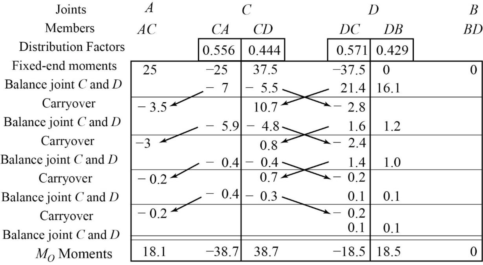
Calculate the fixed end moment for AC.
Calculate the fixed end moment for CA.
Calculate the fixed end moment for CD.
Calculate the fixed end moment for DC.
Calculate the fixed end moment for DB and BD.
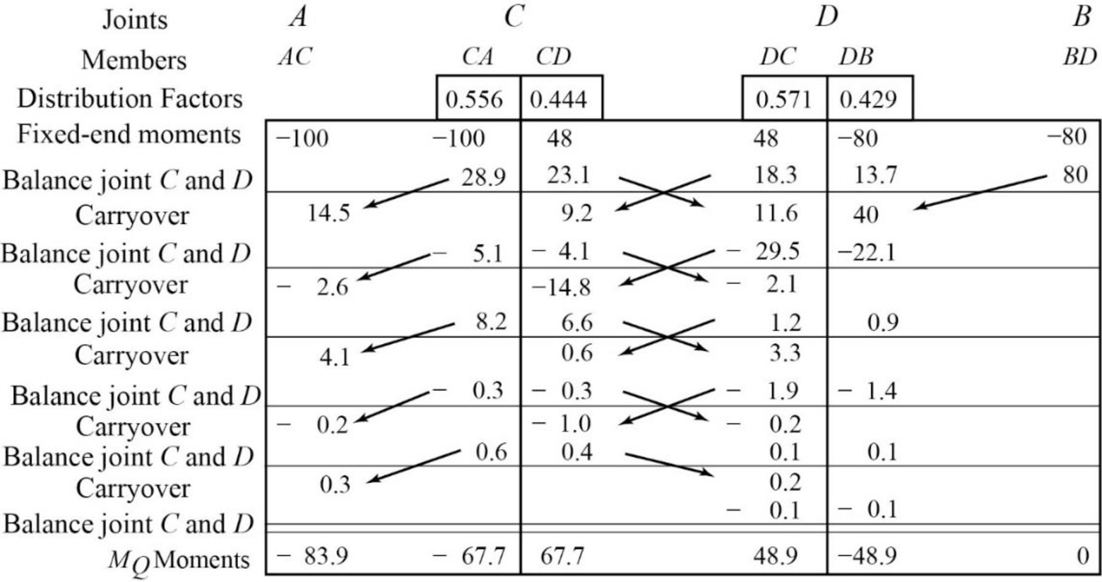
Show the calculation of
Show the free body diagram of the member AC, CD and DB for side-sway prevented as in Figure 2.
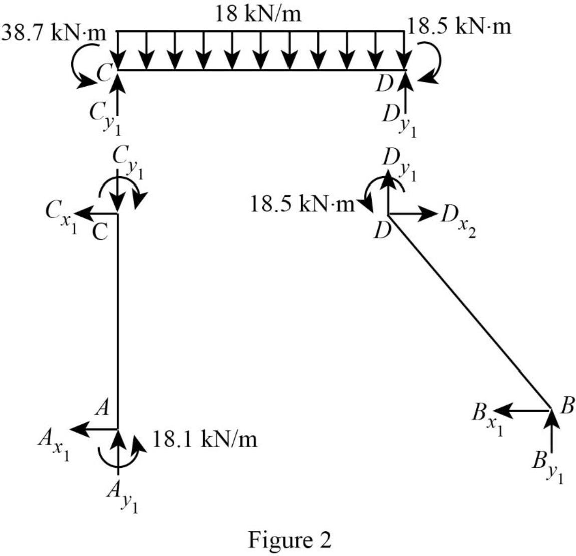
Consider member CD:
Calculate the vertical reaction at the joint C by taking moment about point D.
Calculate the vertical reaction at joint D by resolving the horizontal equilibrium.
Consider member AC
Calculate vertical reaction at joint A using the relation:
Calculate horizontal reaction at joint A by taking moment about point C.
Calculate the horizontal reaction at joint C by resolving the horizontal equilibrium.
Consider member DB:
Calculate vertical reaction at joint B:
Calculate horizontal reaction at joint B by taking moment about point D.
Calculate the horizontal reaction at joint D by resolving the horizontal equilibrium.
Show the unknown load R as in Figure 3.
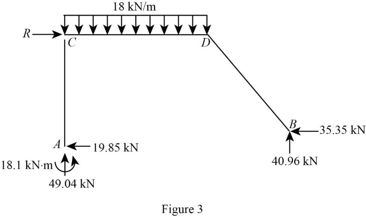
Calculate the reaction R:
Show the arbitrary translation as in Figure 4.
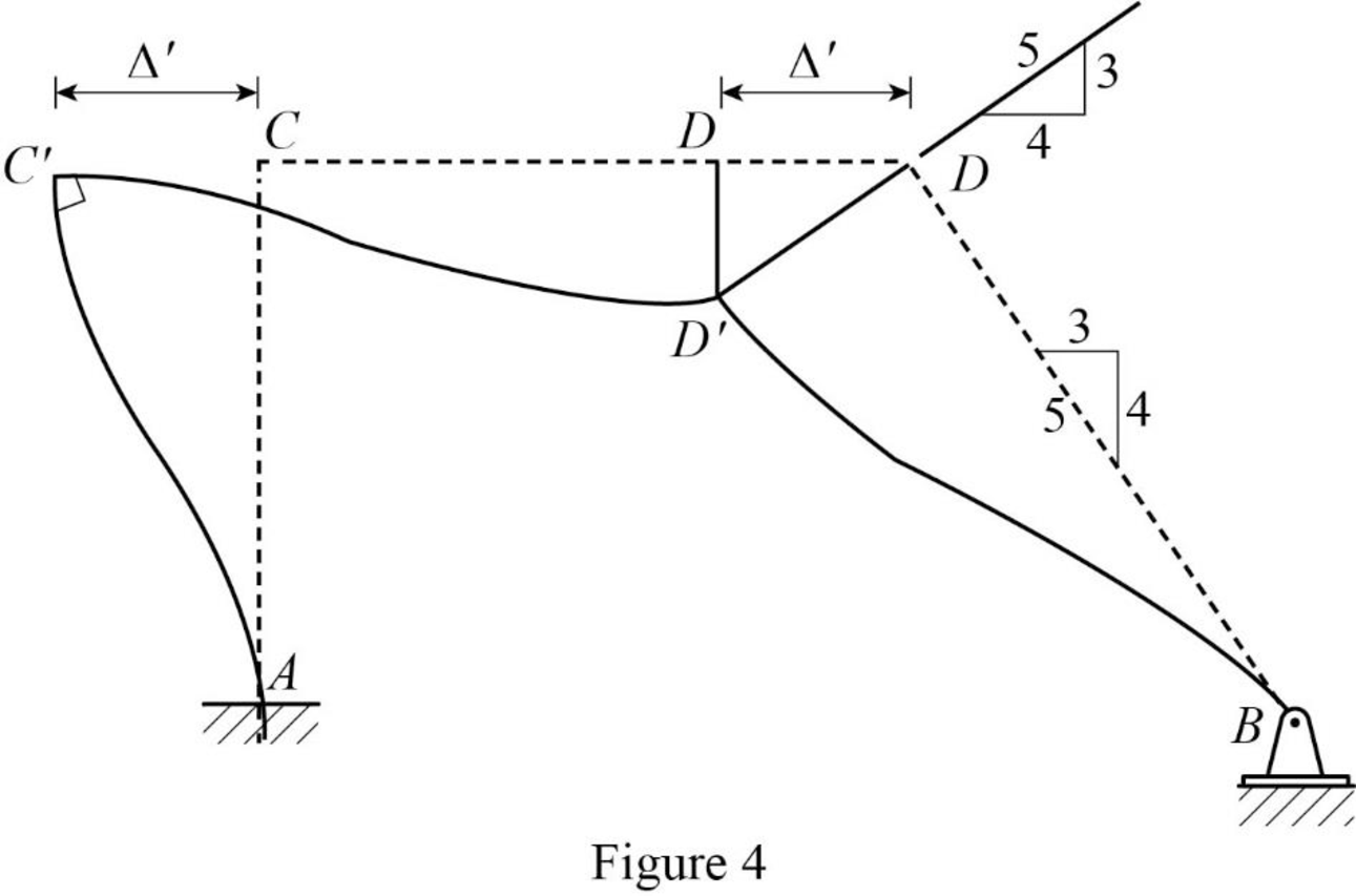
Calculate the relative translation
Calculate the relative translation
Calculate the relative translation
Calculate the fixed end moment for AC and CA.
Substitute
Calculate the fixed end moment for CD and DC.
Substitute
Calculate the fixed end moment for BD and DB.
Substitute
Assume the Fixed-end moment at AC, and CA as
Calculate the value of
Substitute
Calculate the fixed end moment of CD and DC.
Substitute 266.7 for
Calculate the fixed end moment of BD and DB.
Substitute 266.7 for
Show the calculation of
Show the free body diagram of the member AC, CD and DB for side-sway permitted as in Figure 5.
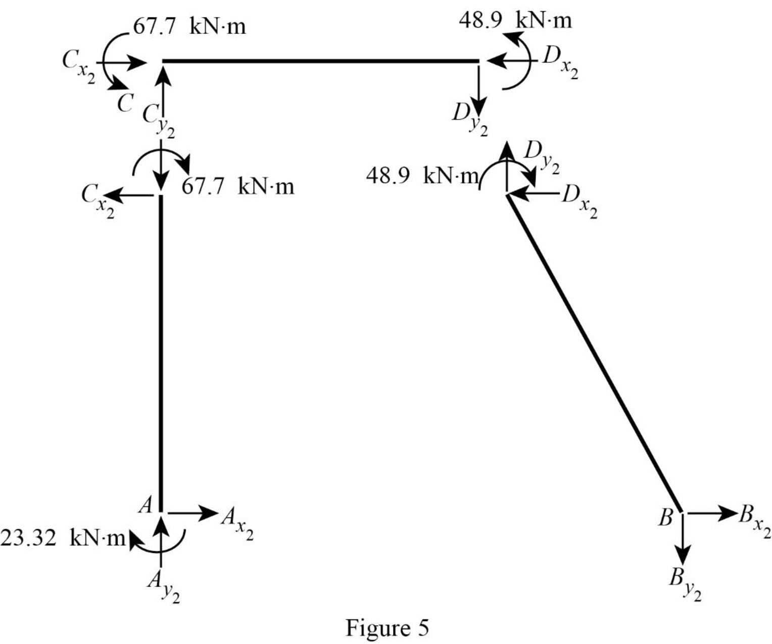
Consider member CD:
Calculate the vertical reaction at the joint C by taking moment about point D.
Calculate the vertical reaction at joint D by resolving the horizontal equilibrium.
Consider member AC
Calculate vertical reaction at joint A using the relation:
Calculate horizontal reaction at joint A by taking moment about point C
Calculate the horizontal reaction at joint C by resolving the horizontal equilibrium.
Consider member DB:
Calculate vertical reaction at joint B:
Calculate horizontal reaction at joint B by taking moment about point D
Calculate the horizontal reaction at joint D by resolving the horizontal equilibrium.
Show the unknown load Q as in Figure 6.
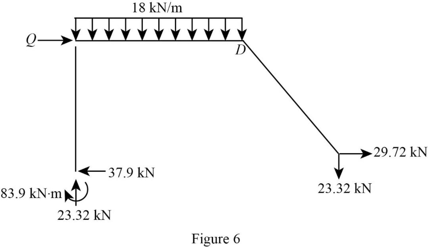
Calculate the reaction Q:
Calculate the actual member end moments of the member AC:
Substitute
Calculate the actual member end moments of the member CA:
Substitute
Calculate the actual member end moments of the member CD:
Substitute
Calculate the actual member end moments of the member DC:
Substitute
Calculate the actual member end moments of the member DB:
Substitute
Calculate the actual member end moments of the member BD:
Substitute
Show the section free body diagram of the member AC, CD, and DB as in Figure 5.
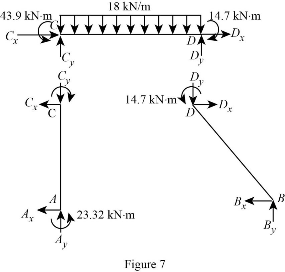
Consider member CD:
Calculate the vertical reaction at the joint C by taking moment about point D.
Calculate the vertical reaction at joint D by resolving the horizontal equilibrium.
Consider member AC
Calculate vertical reaction at joint A:
Calculate horizontal reaction at joint A by taking moment about point C.
Calculate the horizontal reaction at joint C by resolving the horizontal equilibrium.
Consider member DB:
Calculate vertical reaction at joint B using the relation:
Calculate horizontal reaction at joint B.
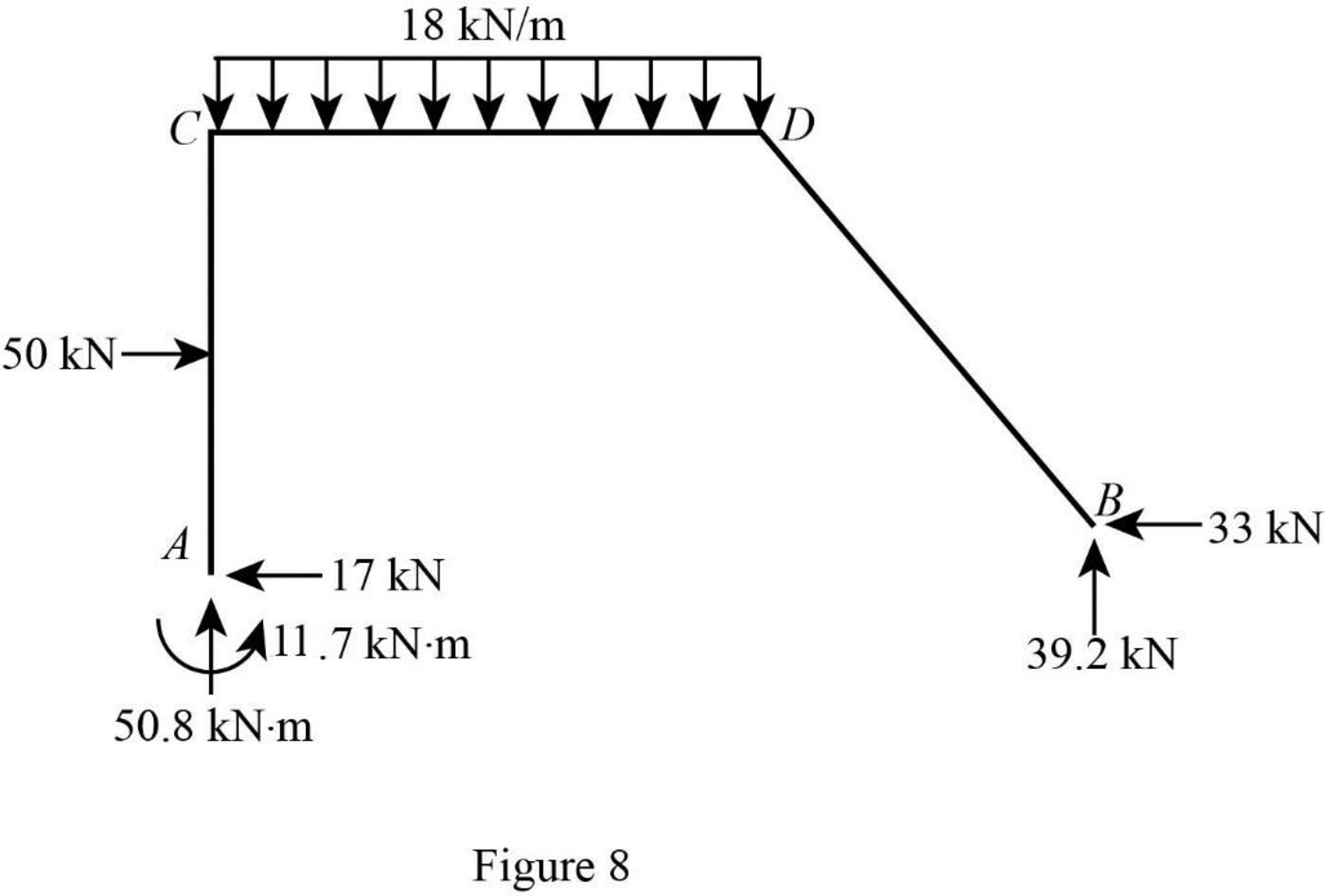
Show the reactions of the frame as in Figure 8.
Want to see more full solutions like this?
Chapter 16 Solutions
Structural Analysis


- S₂ S S,-40 S,-100 P S,=40 40 80 80 40arrow_forwardThe bolted connection shown is connected with M20 bolts in standard holes. The plate material is A36 steel. Find the allowable (ASD) tensile strength of each plate. 50 65 65 65 13 40 65 40 13arrow_forwardA 3.048 m long column (Fy = 483 MPa) carries an axial compression load of 5000 kN dead load. The column is braced at mid-height to strengthen the column in the weak direction. Use LRFD. Which of the following most nearly gives the nominal compressive strength? Show solution and drawingsarrow_forward
- When an open-ended square tube is placed vertically into a pool of water, the water rises 4 mm up inside of the tube. A) Determine the inner length of the square tube. A solid cylindrical rod is then placed vertically down the center of the open-ended square tube and the water rises an additional 4 mm up the tube. B) Determine the diameter of the solid rod that was inserted. 0.073 @ 20N m T C s = = o .arrow_forwardPlease use the following labels in the image such as Va, Vbr, Vbl and etc. Show step by step solution for each. Thanks!arrow_forwardThe single story building shown in Fig. 2 has an applied uniform load of 300 psf (0.3ksf) including the self weight of the beams and the girders. The roof has a 16 ft x 15 ft opening as shown. 1. Determine the axial loads on Columns C1 and C2 using reactions from the beams supported on the columns. 2. Determine the axial loads on Columns C1 and C2 using the concept of tributary areas.arrow_forward
- A built-up beam section is formed by welding 2xL8x6x1 angles to the bottom flange of W36x210 as shown in Fig. 1. Determine the following section properties of the built-up cross section: a. Cross sectional area, A (in2) b. The location of the centroids CG-X and CG-Y id of the built up section from the bottom of angle ( this value is given, so you need to check that you get this value) c. Moments of inertia ICG-X (in4) and ICG-Y (in4) d. Section modulus Sx (bot) (in3) and Sx (top) (in3) e. Radius of gyration rx (in) and ry (in) f. Weight of the built up section, w (lb/ft) (use density of steel = 490 pcf) g. Surface area of the built-up section, S(ft2/ft)arrow_forward11. Design the main beam of a building supporting concrete floor slab as shown in Fig. 10.61 and with the following data: (i) Beam centres: 6 m (ii) Span (simply supported): 7.4 m (iii) Concrete slab (spanning in two directions): 240-mm thick (iv) Finished screed: 40-mm thick (v) Imposed load: 4 kN/m² (vi) Take weight of concrete slab as 24 kN/m³ and total weight of 40-mm thick screed as 1.0 kN/m² Assume Fe 410 grade steel and take initial weight of beam as 1.0 kN/m. H H- Main beam 7.4 m 6.0 m H 40 mm screed I -H. Fig. 10.61 k 240 mm slab 6.0 m Typical bay of large floor areaarrow_forwardConsider the situation in Question 2. If all the cables are made of the same material and have a maximum tensile force of 500 lb, what is the heaviest load that can be supported by the system?arrow_forward
- A flexible circular area is subjected to a uniformly distributed load of 148 (see the figure below). The diameter of the load area is 2 . Estimate the average stress increase () below the center of the loaded area between depths of 3 and 6 . Use the equations: and (Enter your answer to three significant figures.) =arrow_forwardA square flexible foundation of width B applies a uniform pressure go to the underlying ground. (a) Determine the vertical stress increase at a depth of 0.625B below the center using Aσ beneath the corner of a uniform rectangular load given by Aσ = Variation of Influence Value I qoI. Use the table below. n 0.8 1.0 m 0.2 0.4 0.5 0.6 0.2 0.01790 0.03280 0.03866 0.04348 0.05042 0.05471 0.4 0.03280 0.06024 0.07111 0.08009 0.09314 0.10129 0.5 0.03866 0.07111 0.08403 0.09473 0.11035 0.12018 0.6 0.04348 0.08009 0.09473 0.10688 0.12474 0.13605 0.8 0.05042 0.09314 0.11035 0.12474 0.14607 0.15978 1.0 0.05471 0.10129 0.12018 0.13605 0.15978 0.17522 (Enter your answer to three significant figures.) Ασ/90 = (b) Determine the vertical stress increase at a depth of 0.625B below the center using the 2 : 1 method equation below. 90 x B x L Aσ = (B+ z) (L + z) (Enter your answer to three significant figures.) Ασ/90 = (c) Determine the vertical stress increase at a depth of 0.625B below the center using…arrow_forwardPoint loads of magnitude 100, 200, and 360 act at , , and , respectively (in the figure below). Determine the increase in vertical stress at a depth of 6 below point . Use Boussinesq's equation. (Enter your answer to three significant figures.) =arrow_forward