
Laboratory Manual for Introductory Circuit Analysis
13th Edition
ISBN: 9780133923780
Author: Robert L. Boylestad, Gabriel Kousourou
Publisher: PEARSON
expand_more
expand_more
format_list_bulleted
Videos
Textbook Question
Chapter 16, Problem 20P
For the series circuits in Fig. 16.80, find a parallel circuit that will have the same total impedance (ZT).
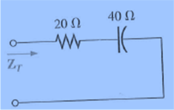
Fig. 16.80
Expert Solution & Answer
Want to see the full answer?
Check out a sample textbook solution
Students have asked these similar questions
Not: I need also pictures
cct diagram and result
Question:
I need a MATLAB/Simulink model for a
Boost Converter used to charge a battery,
powered by a PV solar panel. The model
should include:
1. A PV solar panel as the input power
source.
2. A Boost Converter circuit for voltage
regulation.
3. A battery charging system.
4. Simulation results showing voltage,
current, and efficiency of the system.
Important: Please provide:
1. The Simulink file of the model.
2. Clear screenshots showing the circuit
connections in MATLAB/Simulink.
3. Screenshots of the simulation results
(voltage, current, efficiency, etc.).
NEED HANDWRITTEN SOLUTION PLEASE DO NOT USE AI
Not: I need also pictures
cct diagram and result
Question:
I need a MATLAB/Simulink model for a
Boost Converter used to charge a battery,
powered by a PV solar panel. The model
should include:
1. A PV solar panel as the input power
source.
2. A Boost Converter circuit for voltage
regulation.
3. A battery charging system.
4. Simulation results showing voltage,
current, and efficiency of the system.
Chapter 16 Solutions
Laboratory Manual for Introductory Circuit Analysis
Ch. 16 - Find the total impedance of the parallel networks...Ch. 16 - Find the total impedance of the parallel...Ch. 16 - Prob. 3PCh. 16 - For each configuration of Fig. 16.66: a. Find the...Ch. 16 - For each configuration of Fig. 16.67 a. Find the...Ch. 16 - For each network of Fig. 16.68: a. find the total...Ch. 16 - For the circuit of Fig. 16.69: a. Find the total...Ch. 16 - Given the voltage and current shown in Fig. 16.70,...Ch. 16 - For the network in Fig. 16.71: a. Find the total...Ch. 16 - Repeat Problem 9 for the network in Fig. 16.72,...
Ch. 16 - For the network of Fig. 16.73: a. Find the total...Ch. 16 - For the network in Fig. 16.74: a. Find the total...Ch. 16 - Repeat Problem 12 for the circuit in Fig. 16.75...Ch. 16 - Calculate the currents I1 and I2 in Fig. 16.76 in...Ch. 16 - For the parallel R-C network in Fig. 16.77: a....Ch. 16 - For the parallel R-L network in Fig. 16.78: a....Ch. 16 - Plot YTandT(ofYT=YTT) for a frequency range of...Ch. 16 - Plot YTandT(ofYT=YTT) for a frequency range of...Ch. 16 - For the parallel R-L-C network in Fig. 16.79. a....Ch. 16 - For the series circuits in Fig. 16.80, find a...Ch. 16 - For the parallel circuits in Fig. 16.81, find a...Ch. 16 - For the network in Fig. 16.82: a. Calculate E, IR,...Ch. 16 - Find the element or elements that must be in the...Ch. 16 - For the network in Fig. 16.13 (usef=1kHz): a....Ch. 16 - For the network in Fig. 16.32: a. Plot the...
Knowledge Booster


Learn more about
Need a deep-dive on the concept behind this application? Look no further. Learn more about this topic, electrical-engineering and related others by exploring similar questions and additional content below.Similar questions
- 2. Design the boost converter with the following specifications: Vin = 28 V, Vo = 48 V, Po = 100 W, fs = 110 kHz Sketch the inductor current. The converter is in CCM.arrow_forwardI need help with this problem and an explanation of the solution for the image described below. (Introduction to Signals and Systems)arrow_forwardI need solutions to this project question, expertly solve darrow_forward
- HANDWRITTEN SOLUTION NOT USING AIUsing nodal analysis, find V_o in the networkarrow_forwardYour objective is to obtain a Th´evenin equivalent for thecircuit shown in Fig. P7.46, given that is(t) = 3cos 4×10⁴t A. Tothat end:(a) Transform the circuit to the phasor domain.(b) Apply the source-transformation technique to obtain theTh´evenin equivalent circuit at terminals (a,b). (c) Transform the phasor-domain Th´evenin circuit back to thetime domain.arrow_forward7.48 Determine the Thévenin equivalent of the circuit in Fig. P7.48 at terminals (a,b), given that Us(t) 12 cos 2500t V, = is(t)=0.5 cos (2500t - 30°) A.arrow_forward
- Power system studies on an existing system have indicated that 2400 MW are to be transmitted for a distance of 400 Km. The voltage levels being considered include 345 kV, 500 kV, and 765 kV. For a preliminary design based on the practical line loadability, you may assume the following surge impedances 345 kV Zc=320 2 500 kV Zc=290 765 kV Zc=265 The line wavelength may be assumed to be 5000 km. The practical line loadability may be based on a load angle of 35º. Assume |Vs| = 1.0 pu and |Vr|=0.9 pu. a) Determine the number of three-phase transmission circuits required for each voltage level. Each transmission tower may have up to two circuits. To limit the corona loss, all 500-kV lines must have at least two conductors per phase, and all 765-kV lines must have at least four conductors per phase. b) The bundle spacing is 45 cm. The conductor size should be such that the line would be capable of carrying current corresponding to at least 5000 MVA. Determine the number of conductors in the…arrow_forwardGiven handwritten correct solution do not use AIarrow_forwardDon't use ai to answer I will report you answerarrow_forward
arrow_back_ios
SEE MORE QUESTIONS
arrow_forward_ios
Recommended textbooks for you
 Introductory Circuit Analysis (13th Edition)Electrical EngineeringISBN:9780133923605Author:Robert L. BoylestadPublisher:PEARSON
 Delmar's Standard Textbook Of ElectricityElectrical EngineeringISBN:9781337900348Author:Stephen L. HermanPublisher:Cengage Learning
 Programmable Logic ControllersElectrical EngineeringISBN:9780073373843Author:Frank D. PetruzellaPublisher:McGraw-Hill Education
 Fundamentals of Electric CircuitsElectrical EngineeringISBN:9780078028229Author:Charles K Alexander, Matthew SadikuPublisher:McGraw-Hill Education
 Electric Circuits. (11th Edition)Electrical EngineeringISBN:9780134746968Author:James W. Nilsson, Susan RiedelPublisher:PEARSON
 Engineering ElectromagneticsElectrical EngineeringISBN:9780078028151Author:Hayt, William H. (william Hart), Jr, BUCK, John A.Publisher:Mcgraw-hill Education,
Introductory Circuit Analysis (13th Edition)
Electrical Engineering
ISBN:9780133923605
Author:Robert L. Boylestad
Publisher:PEARSON
Delmar's Standard Textbook Of Electricity
Electrical Engineering
ISBN:9781337900348
Author:Stephen L. Herman
Publisher:Cengage Learning
Programmable Logic Controllers
Electrical Engineering
ISBN:9780073373843
Author:Frank D. Petruzella
Publisher:McGraw-Hill Education
Fundamentals of Electric Circuits
Electrical Engineering
ISBN:9780078028229
Author:Charles K Alexander, Matthew Sadiku
Publisher:McGraw-Hill Education
Electric Circuits. (11th Edition)
Electrical Engineering
ISBN:9780134746968
Author:James W. Nilsson, Susan Riedel
Publisher:PEARSON
Engineering Electromagnetics
Electrical Engineering
ISBN:9780078028151
Author:Hayt, William H. (william Hart), Jr, BUCK, John A.
Publisher:Mcgraw-hill Education,
Mesh Current Problems in Circuit Analysis - Electrical Circuits Crash Course - Beginners Electronics; Author: Math and Science;https://www.youtube.com/watch?v=DYg8B-ElK0s;License: Standard Youtube License