
Concept explainers
Videos
Find the total impedance of the parallel networks of Fig. 1663 in rectangular and polar form.
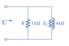
Fig. 1663
(a)
Total impedance of the given network.
Answer to Problem 1P
Rectangular form:
Polar form:
Explanation of Solution
Given:
The given network is:
Calculation:
We can see from the given circuit that the resistor
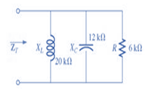
(b)
Total impedance of the given network.
Answer to Problem 1P
Rectangular form:
Polar form:
Explanation of Solution
Given:
The given network is:
Calculation:
We can see from the given circuit that the resistor
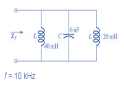
(c)
Total impedance of the given network.
Answer to Problem 1P
Rectangular form:
Polar form:
Explanation of Solution
Given:
The given network is:
Calculation:
We can see from the given circuit that two inductors and one capacitor are connected in parallel.
Therefore, we need to calculate their equivalent reactance first:
Inductive reactance of
Inductive reactance of
Capacitive reactance of
Therefore, the total resistance of the network will be:
Want to see more full solutions like this?
Chapter 16 Solutions
Introductory Circuit Analysis (13th Edition)
Additional Engineering Textbook Solutions
Elementary Surveying: An Introduction To Geomatics (15th Edition)
Mechanics of Materials (10th Edition)
Starting Out with Programming Logic and Design (5th Edition) (What's New in Computer Science)
Starting Out with C++: Early Objects (9th Edition)
Starting Out with Java: From Control Structures through Data Structures (4th Edition) (What's New in Computer Science)
Database Concepts (8th Edition)


- Ideal op-amps. R)1= 16 kΩ and R)2= 56 kΩ. Find the voltage gain v_o/v_i of the circuit.arrow_forwardR is 12 kΩ . Find the Thevenin equivalent resistance.arrow_forwardAssuming an ideal op-amp, design an inverting amplifier with a gain of 25 dB having the largest possible input resistance under the constraint of having to use resistors no larger than 90 kΩ. What's the input resist?arrow_forward
- I need help with this problem and an explanation of the solution for the image described below. (Introduction to Signals and Systems)arrow_forwardI hope the solution is on paper and not artificial intelligence. The subject is control systemarrow_forwardI hope the solution is on paper and not artificial intelligence.arrow_forward
- Vs R1 R2 ww ww 21x R3 Define the Thevenin equivalent of the above circuit where R1= 10 52, R2= 30 S2, R3 = 30 12, Vs = 70 V. VThevenin Number V RThevenin = Number Ωarrow_forwardR1 ww + R3 15+ www R2 R4 ww With the circuit diagram shown above and the values of the circuit elements listed below, find i1, 12, v1, and v2. Is = 10A, R1 = 7 ohms, R2 = 9 ohms, R3 = 7 ohms, R4 = 8 ohms (a) i1 = Number A (b) 12 = Number A (c) v1 = Number V (d) v2 = Number Varrow_forward15 ww 22 R2 ли i4 1+ V4 R1 ww R3 Solve for current i4 using superposition where R1 = 902, R2 = 36052, R3 = 360 V, and 15 = 5 A. 27052, V4 = i4 due to voltage source (V4) alone: Number A i4 due to current source (15) alone: Number A i4 = Numberarrow_forward
 Delmar's Standard Textbook Of ElectricityElectrical EngineeringISBN:9781337900348Author:Stephen L. HermanPublisher:Cengage Learning
 Power System Analysis and Design (MindTap Course ...Electrical EngineeringISBN:9781305632134Author:J. Duncan Glover, Thomas Overbye, Mulukutla S. SarmaPublisher:Cengage Learning