Concept explainers
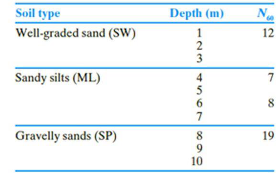
The following table shows the boring log at a site where a multi-story shopping center would be constructed. Soil classification and the standard penetration number, N60, are provided in the boring log. All columns of the building are supported by square footings which must be placed at a depth of 1.5 m. Additionally, the settlement (elastic) of each footing must be restricted to 20 mm. Since the column loads at different location can vary, a design chart is helpful for quick estimation of footing size required to support a given load.
- a. Prepare a chart by plotting the variation of maximum allowable column loads with footing sizes, B = 1 m, 1.5 m, 2 m, and 3 m. Use a factor of safety of 3.
- b. If the gross column load from the structure is 250 kN, how would you use this chart to select a footing size?
- c. What would be the design footing size for the column in Part (b) if you use Terzaghi’s bearing capacity equation? For the well graded sand, assume that ϕ′ = 33°. Use Fs = 3.
- d. Compare and discuss the differences in footing sizes obtained in Parts b and c.

(a)
Plot the variation of maximum allowable column loads with size of footings to prepare a chart.
Explanation of Solution
Given information:
The location of depth of footing
The given size of the footing B is 1 m, 1.5 m, 2 m, and 3 m.
The settlement of each footing
The given factor of safety
Calculation:
For B value is 1 m:
Determine the depth factor using the relation.
Substitute 1.5 m for
The
The field standard penetration number
Determine the depth of foundation for the field standard penetration number gets averaged.
Substitute 1.5 m for
Determine the averaged
Here,
Substitute 12 for
Determine the net allowable bearing capacity of the soil
Substitute 10 for
Determine the maximum allowable column load
Substitute
For B value is 1.5 m:
Determine the depth factor using the relation.
Substitute 1.5 m for
The field standard penetration number
Determine the depth of foundation for the field standard penetration number gets averaged.
Substitute 1.5 m for
Determine the averaged
Here,
Substitute 7 for
Determine the net allowable bearing capacity of the soil
Substitute 8 for
Determine the maximum allowable column load
Substitute
For B value is 2 m:
Determine the depth factor using the relation.
Substitute 1.5 m for
The field standard penetration number
Determine the depth of foundation for the field standard penetration number gets averaged.
Substitute 1.5 m for
Determine the averaged
Substitute 12 for
Determine the net allowable bearing capacity of the soil
Substitute 9 for
Determine the maximum allowable column load
Substitute
For B value is 3 m:
Determine the depth factor using the relation.
Substitute 1.5 m for
The field standard penetration number
Determine the depth of foundation for the field standard penetration number gets averaged.
Substitute 1.5 m for
Determine the averaged
Here,
Substitute 12 for
Determine the net allowable bearing capacity of the soil
Substitute 12 for
Determine the maximum allowable column load
Substitute
Summarize the calculated values as in Table (1).
| Width B (m) | Column load (kN) |
| 1 | 71 |
| 1.5 | 115 |
| 2 | 198 |
| 3 | 507.5 |
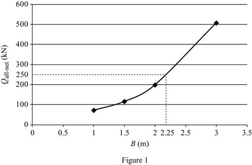
Plot the graph between the size of the footing and the column load as in Figure (1).

(b)
Find the footing size for the given gross column load of 250 kN.
Answer to Problem 16.1CTP
The footing size for the given gross column load of 250 kN is
Explanation of Solution
Given information:
The location of depth of footing
The given size of the footing B is 1 m, 1.5 m, 2 m, and 3 m.
The settlement of each footing
The given factor of safety
Calculation:
Refer Figure (1).
The size of the footing is 2.25 m for the gross column load of 250 kN.
Therefore, the footing size for the given gross column load of 250 kN is
(c)
Find the design column load for the footing size of 2.25 m using the Terzaghi’s bearing capacity equation.
Answer to Problem 16.1CTP
The design column load for the footing size of 2.25 m using the Terzaghi’s bearing capacity equation is
Explanation of Solution
Given information:
The value of cohesion
The soil friction angle
The location of depth of footing base
The width of the footing B is 2.25 m.
The given factor of safety
Calculation:
Determine the net ultimate bearing capacity of the soil
Here,
Take the unit weight of the soil
Refer Table 16.1, “Terzaghi’s bearing-capacity factors–
Take the
Substitute
Determine the net allowable bearing capacity
Substitute
Therefore, the design column load for the footing size of 2.25 m using the Terzaghi’s bearing capacity equation is
(d)
Compare and discuss the differences in footing sizes obtained in parts (b) and (c).
Explanation of Solution
Given information:
The soil friction angle
The location of depth of footing base
The width of the footing B is 2.25 m.
The given factor of safety
Calculation:
The net allowable column load obtained by using Terzaghi’s bearing capacity equation (2,173 kN) is significantly higher than the method based on the
Want to see more full solutions like this?
Chapter 16 Solutions
EBK PRINCIPLES OF GEOTECHNICAL ENGINEER
- Draw the shear force and bending moment diagramarrow_forwardThe pin-connected structure consists of a rigid beam ABCD and two supporting bars. Bar (1) is an aluminum alloy [E = 75 GPa] with a cross-sectional area of A₁ = 850 mm². Bar (2) is a bronze alloy [E = 109 GPa] with a cross-sectional area of A₂ = 410 mm². Assume L₁=2.6 m, L₂-3.3 m, a=0.7 m, b=1.5 m, and c=0.8 m. All bars are unstressed before the load P is applied; however, there is a 4.5-mm clearance in the pin connection at A. If a load of P = 45 kN is applied at B, determine: (a) the normal stresses σ1,02, in both bars (1) and (2). (b) the normal strains €1, €2, in bars (1) and (2). (c) determine the downward deflection VA of point A on the rigid bar. (1) Answers: a (a) σ1 = (b) E₁ = (C) VA = i i i ล B C L2 b C MPa, σ = i με, Ε2 i mm. MPa. μεarrow_forwardThe pin-connected structure consists of a rigid beam ABCD and two supporting bars. Bar (1) is an aluminum alloy [E = 79 GPa] with a cross-sectional area of A₁ = 780 mm². Bar (2) is a bronze alloy [E = 104 GPa] with a cross-sectional area of A₂ = 460 mm². Assume L₁=1.6 m, L₂-2.1 m, a=0.6 m, b=1.8 m, and c-1.3 m. All bars are unstressed before the load P is applied; however, there is a 4-mm clearance in the pin connection at A. If a load of P = 58 kN is applied at B, determine: (a) the normal stresses 01,02, in both bars (1) and (2). (b) the normal strains €1,2, in bars (1) and (2). (c) determine the downward deflection VA of point A on the rigid bar. (1) L₁ B Answers: (a)σ = b ล L2 C D i MPa, σ1 = i MPa. με, Ε2 = i με. (b) €1 = i (C) VA = i mm.arrow_forward
- A load of P = 114 kN is supported by a structure consisting of rigid bar ABC, two identical solid bronze [E = 116 GPa] rods, and a solid steel [E=192 GPa] rod, as shown. The bronze rods (1) each have a diameter of 19 mm and they are symmetrically positioned relative to the center rod (2) and the applied load P. Steel rod (2) has a diameter of 28 mm. All bars are unstressed before the load P is applied; however, there is a 1.5-mm clearance in the bolted connection at B. Assume L₁ = 2.4 m and L₂ = 1.5 m. Determine: (a) the normal stresses in the bronze and steel rods (01, 02). (b) the downward deflection of rigid bar ABC. (1) Answers: L2 (a) σ1 (b) v = = i i B (1) MPa, 02 mm. = i MPa.arrow_forwardA load of P = 114 kN is supported by a structure consisting of rigid bar ABC, two identical solid bronze [E = 116 GPa] rods, and a solid steel [E=192 GPa] rod, as shown. The bronze rods (1) each have a diameter of 19 mm and they are symmetrically positioned relative to the center rod (2) and the applied load P. Steel rod (2) has a diameter of 28 mm. All bars are unstressed before the load P is applied; however, there is a 1.5-mm clearance in the bolted connection at B. Assume L₁ = 2.4m and L2 = 1.5 m. Determine: (a) the normal stresses in the bronze and steel rods (01,02). (b) the downward deflection of rigid bar ABC. (1) Answers: (a)σ1 = (b) vi L2 (2) (1) B P mm. Li MPa, 02 MPa. =arrow_forwardA high-density polvethelene (HD PE I9 - 780 MPaiy = 0.46 rod has a diameter of 70 mm before load Pis applied. In order to maintain certain clearances, the diameter of the rod must not exceed 72 mm when loaded. What is the largest permissible compressive load P that can be applied to the HDPE rod?arrow_forward
- Current Attempt in Progress A load of P 117 kN is supported by a structure consisting of rigid bar ABC, two identical solid bronze [E= 83 GPa] rods, and a solid steel [E 182 GPa] rod, as shown. The bronze rods (1) each have a diameter of 20 mm and they are symmetrically positioned relative to the center rod (2) and the applied load P. Steel rod (2) has a diameter of 26 mm. All bars are unstressed before the load Pis applied; however, there is a 3.4-mm clearance in the bolted connection at B. Assume L₁ = 3.3 m and L2 = 1.6 m. Determine: (a) the normal stresses in the bronze and steel rods (01, 02). (b) the downward deflection v of rigid bar ABC. (1) Answers: L2 (2) (1) B P (a) σ = (b) y = eTextbook and Media Save for Later MPa. MPa, 02 = mm. Attempts: 0 of 5 used Submit Answerarrow_forwardA vinyl [E= 2.60 GPa; v = 0.43] block with width b = 50 mm, depth d = 100 mm, and height h = 270 mm rests on a smooth rigid base. A load P is applied to a rigid plate that rests on top of the block. Calculate the change in the depth dimension d of the block after a load of P = 120 kN is applied. Rigid plate Answer: Ad= Width b Depth d Height Rigid base mmarrow_forwardAn aluminum [E = 11900 ksi] control rod with a circular cross section must not stretch more than 0.24 in. when the tension in the rod is 1980 lb. If the maximum allowable normal stress in the rod is 12.1 ksi, determine: (a) the smallest diameter d that can be used for the rod. (b) the corresponding maximum length L of the rod. Answers: (a) d = i (b) L = i in. in.arrow_forward
- View Policies Current Attempt in Progress At an axial load of 19 kN, a 45-mm-wide by 15-mm-thick polyimide polymer bar elongates 2.7 mm while the bar width contracts 0.19 mm. The bar is 220 mm long. At the 19-kN load, the stress in the polymer bar is less than its proportional limit. Determine (a) the modulus of elasticity. (b) Poisson's ratio. (c) the change in the bar thickness. Answers: (a) E= (b) v= (c) Athickness eTextbook and Media Save for Later GPa mm Attempts: 0 of 5 used Submit Answerarrow_forwardIn the two-member assembly shown, find the axial force in rod (1) if P = 11.3 kips. 8 ft 12 ft O 4.45 kips 8.53 kips 9.38 kips O 7.24 kips 6.76 kips B 16 ftarrow_forwardFigure 3 shows the numerical solution of the advection equation for a scalar u along x at threeconsecutive timesteps.Provide an explanation what conditions and numerical setup could explain the curves. Identifywhich of the three curves is the first, second and third timestep.arrow_forward
 Principles of Geotechnical Engineering (MindTap C...Civil EngineeringISBN:9781305970939Author:Braja M. Das, Khaled SobhanPublisher:Cengage Learning
 Principles of Foundation Engineering (MindTap Cou...Civil EngineeringISBN:9781337705028Author:Braja M. Das, Nagaratnam SivakuganPublisher:Cengage Learning
 Fundamentals of Geotechnical Engineering (MindTap...Civil EngineeringISBN:9781305635180Author:Braja M. Das, Nagaratnam SivakuganPublisher:Cengage Learning
 Principles of Foundation Engineering (MindTap Cou...Civil EngineeringISBN:9781305081550Author:Braja M. DasPublisher:Cengage Learning
 Construction Materials, Methods and Techniques (M...Civil EngineeringISBN:9781305086272Author:William P. Spence, Eva KultermannPublisher:Cengage Learning


