
Vector Mechanics for Engineers: Statics and Dynamics
12th Edition
ISBN: 9781259638091
Author: Ferdinand P. Beer, E. Russell Johnston Jr., David Mazurek, Phillip J. Cornwell, Brian Self
Publisher: McGraw-Hill Education
expand_more
expand_more
format_list_bulleted
Concept explainers
Videos
Textbook Question
Chapter 15.3, Problem 15.103P
Using the method of Sec. 15.3, solve Prob. 15.65.
15.65 Linkage DBEF is part of a windshield wiper
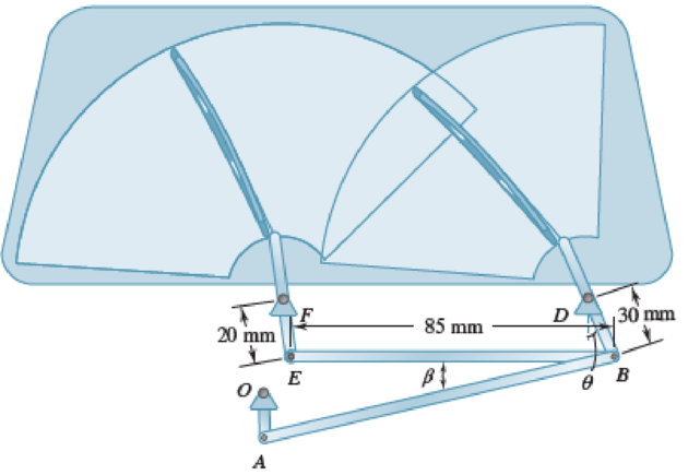
Fig. P15.65
Expert Solution & Answer
Want to see the full answer?
Check out a sample textbook solution
Students have asked these similar questions
CORRECT AND DETAILED HANDWRITTEN SOLUTION WITH FBD ONLY. I WILL UPVOTE THANK YOU. CORRECT ANSWER IS ALREADY PROVIDED.
Answers:
P1 = 208.625 KN/M
P2 = 281.310 KN/M
P = 15.491 KN/M
FB = 463.402 MPA
FV = 55.034 MPA
CORRECT AND DETAILED HANDWRITTEN SOLUTION WITH FBD ONLY. I WILL UPVOTE THANK YOU. CORRECT ANSWER IS ALREADY PROVIDED.
18: Determine the maximum shear and moment that would be experienced by a 10 m beam if a three-wheelmoving load of 10 kN, 30 kN, and 5 kN respectively will pass it by. The distance between the 1st and 2nd load is 1 m and the distance between the 2nd and 3rd load is 3 m.ANS: Vmax = 40 kN ; Mmax = 100.014 kN-m
CORRECT AND DETAILED HANDWRITTEN SOLUTION WITH FBD ONLY. I WILL UPVOTE THANK YOU. CORRECT ANSWER IS ALREADY PROVIDED.
5: A 12-m simply supported bridge is constructed with 100-mm concrete slab deck supported by precastconcrete stringers spaced 800 mm on center. Analyze the stringers when subjected to a moving load consisting of 3 evenly spaced axle loads at 3 m and equivalent to 20 kN, 30 kN and 40 kN respectively. The self-weight of the stringers is 8.5 kN/m and the concrete deck has a unit weight of 24 kN/m3 . Neglect all other superimposed loads. Calculate: (a) the maximum shear force in the stringers; (b) the maximum bending moment in the stringers.
Answer: Vmax = 135.020 KN, Mmax = 477.388 KN-M
Chapter 15 Solutions
Vector Mechanics for Engineers: Statics and Dynamics
Ch. 15.1 - A rectangular plate swings from arms of equal...Ch. 15.1 - Knowing that wheel A rotates with a constant...Ch. 15.1 - The brake drum is attached to a larger flywheel...Ch. 15.1 - The motion of an oscillating flywheel is defined...Ch. 15.1 - The motion of an oscillating flywheel is defined...Ch. 15.1 - As steam is slowly injected into a turbine, the...Ch. 15.1 - A small grinding wheel is attached to the shaft of...Ch. 15.1 - A connecting rod is supported by a knife-edge at...Ch. 15.1 - Prob. 15.7PCh. 15.1 - The angular acceleration of an oscillating disk is...
Ch. 15.1 - The angular acceleration of a shaft is defined by...Ch. 15.1 - The assembly shown consists of two rods and a...Ch. 15.1 - In Prob. 15.10, determine the velocity and...Ch. 15.1 - Prob. 15.12PCh. 15.1 - The rectangular block shown rotates about the...Ch. 15.1 - A circular plate of 120-mm radius is supported by...Ch. 15.1 - Prob. 15.15PCh. 15.1 - Prob. 15.16PCh. 15.1 - The earth makes one complete revolution on its...Ch. 15.1 - The sprocket wheel and chain shown are initially...Ch. 15.1 - Prob. 15.19PCh. 15.1 - Prob. 15.20PCh. 15.1 - The rated speed of drum B of the belt sander shown...Ch. 15.1 - The two pulleys shown may be operated with the V...Ch. 15.1 - A cyclist uses a stationary trainer during the...Ch. 15.1 - A gear reduction system consists of three gears A,...Ch. 15.1 - A belt is pulled to the right between cylinders A...Ch. 15.1 - Prob. 15.26PCh. 15.1 - Prob. 15.27PCh. 15.1 - A plastic film moves over two drums. During a 4-s...Ch. 15.1 - Cylinder A is moving downward with a velocity of 3...Ch. 15.1 - The system shown is held at rest by the...Ch. 15.1 - A load is to be raised 20 ft by the hoisting...Ch. 15.1 - A simple friction drive consists of two disks A...Ch. 15.1 - Prob. 15.33PCh. 15.1 - Two friction disks A and B are to be brought into...Ch. 15.1 - Two friction disks A and B are brought into...Ch. 15.1 - Steel tape is being wound onto a spool that...Ch. 15.1 - In a continuous printing process, paper is drawn...Ch. 15.2 - The ball rolls without slipping on the fixed...Ch. 15.2 - Three uniform rodsABC, DCE, and FGHare connected...Ch. 15.2 - Prob. 15.38PCh. 15.2 - An overhead door is guided by wheels at A and B...Ch. 15.2 - A painter is halfway up a 10-m ladder when the...Ch. 15.2 - Rod AB can slide freely along the floor and the...Ch. 15.2 - Rod AB can slide freely along the floor and the...Ch. 15.2 - Rod AB moves over a small wheel at C while end A...Ch. 15.2 - The disk shown moves in the xy plane. Knowing that...Ch. 15.2 - The disk shown moves in the xy plane. Knowing that...Ch. 15.2 - Prob. 15.46PCh. 15.2 - Velocity sensors are placed on a satellite that is...Ch. 15.2 - In the planetary gear system shown, the radius of...Ch. 15.2 - Prob. 15.49PCh. 15.2 - The outer gear C rotates with an angular velocity...Ch. 15.2 - Prob. 15.51PCh. 15.2 - A simplified gear system for a mechanical watch is...Ch. 15.2 - 15.53 and 15.54Arm ACB rotates about point C with...Ch. 15.2 - 15.53 and 15.54Arm ACB rotates about point C with...Ch. 15.2 - Knowing that at the instant shown the angular...Ch. 15.2 - Knowing that at the instant shown the velocity of...Ch. 15.2 - Knowing that the disk has a constant angular...Ch. 15.2 - The disk has a constant angular velocity of 20...Ch. 15.2 - The test rig shown was developed to perform...Ch. 15.2 - Prob. 15.60PCh. 15.2 - In the engine system shown, l = 160 mm and b = 60...Ch. 15.2 - In the engine system shown, l = 160 mm and b = 60...Ch. 15.2 - Knowing that the angular velocity of rod DE is a...Ch. 15.2 - In the position shown, bar AB has an angular...Ch. 15.2 - Prob. 15.65PCh. 15.2 - Prob. 15.66PCh. 15.2 - Prob. 15.67PCh. 15.2 - Prob. 15.68PCh. 15.2 - For the oil pump rig shown, link AB causes the...Ch. 15.2 - Both 6-in.-radius wheels roll without slipping on...Ch. 15.2 - The 80-mm-radius wheel shown rolls to the left...Ch. 15.2 - For the gearing shown, derive an expression for...Ch. 15.3 - The disk rolls without sliding on the fixed...Ch. 15.3 - Prob. 15.6CQCh. 15.3 - A juggling club is thrown vertically into the air....Ch. 15.3 - At the instant shown during deceleration, the...Ch. 15.3 - A helicopter moves horizontally in the x direction...Ch. 15.3 - Prob. 15.76PCh. 15.3 - Prob. 15.77PCh. 15.3 - Prob. 15.78PCh. 15.3 - In order to uncoil electrical wire from a spool...Ch. 15.3 - The arm ABC rotates with an angular velocity of 4...Ch. 15.3 - The double gear rolls on the stationary left rack...Ch. 15.3 - Prob. 15.82PCh. 15.3 - Rod ABD is guided by wheels at A and B that roll...Ch. 15.3 - Knowing that at the instant shown the angular...Ch. 15.3 - Knowing that at the instant shown the velocity of...Ch. 15.3 - A motor at O drives the windshield wiper mechanism...Ch. 15.3 - Prob. 15.88PCh. 15.3 - Small wheels have been attached to the ends of bar...Ch. 15.3 - Prob. 15.90PCh. 15.3 - The disk is released from rest and rolls down the...Ch. 15.3 - Prob. 15.92PCh. 15.3 - Two identical rods ABF and DBE are connected by a...Ch. 15.3 - Arm ABD is connected by pins to a collar at B and...Ch. 15.3 - Two rods ABD and DE are connected to three collars...Ch. 15.3 - Two 500-mm rods are pin-connected at D as shown....Ch. 15.3 - At the instant shown, the velocity of collar A is...Ch. 15.3 - Prob. 15.98PCh. 15.3 - Describe the space centrode and the body centrode...Ch. 15.3 - Describe the space centrode and the body centrode...Ch. 15.3 - Prob. 15.101PCh. 15.3 - Using the method of Sec. 15.3, solve Prob. 15.64....Ch. 15.3 - Using the method of Sec. 15.3, solve Prob. 15.65....Ch. 15.3 - Using the method of Sec. 15.3, solve Prob. 15.38....Ch. 15.4 - A rear-wheel-drive car starts from rest and...Ch. 15.4 - Fig. P15.105 and P15.106 15.105A 5-m steel beam is...Ch. 15.4 - For a 5-m steel beam AE, the acceleration of point...Ch. 15.4 - A 900-mm rod rests on a horizontal table. A force...Ch. 15.4 - In Prob. 15.107, determine the point of the rod...Ch. 15.4 - Knowing that point A is moving to the right at a...Ch. 15.4 - Knowing that at the instant shown crank BC has a...Ch. 15.4 - An automobile travels to the left at a constant...Ch. 15.4 - The 18-in.-radius flywheel is rigidly attached to...Ch. 15.4 - 15.113 and 15.114A 3-in.-radius drum is rigidly...Ch. 15.4 - 15.113 and 15.114A 3-in.-radius drum is rigidly...Ch. 15.4 - A heavy crate is being moved a short distance...Ch. 15.4 - Prob. 15.116PCh. 15.4 - The 100-mm-radius drum rolls without slipping on a...Ch. 15.4 - In the planetary gear system shown, the radius of...Ch. 15.4 - The 200-mm-radius disk rolls without sliding on...Ch. 15.4 - Knowing that crank AB rotates about point A with a...Ch. 15.4 - Knowing that crank AB rotates about point A with a...Ch. 15.4 - In the two-cylinder air compressor shown, the...Ch. 15.4 - The right leg of an athlete on a rowing machine...Ch. 15.4 - Arm AB has a constant angular velocity of 16 rad/s...Ch. 15.4 - Arm AB has a constant angular velocity of 16 rad/s...Ch. 15.4 - A straight rack rests on a gear of radius r = 3...Ch. 15.4 - The elliptical exercise machine has fixed axes of...Ch. 15.4 - The elliptical exercise machine has fixed axes of...Ch. 15.4 - Knowing that the angular velocity of rod DE is a...Ch. 15.4 - Knowing that at the instant shown bar DE has an...Ch. 15.4 - 15.131 and 15.132Knowing that at the instant shown...Ch. 15.4 - 15.131 and 15.132Knowing that at the instant shown...Ch. 15.4 - 15.133 and 15.134Knowing that at the instant shown...Ch. 15.4 - 15.133 and 15.134Knowing that at the instant shown...Ch. 15.4 - Prob. 15.135PCh. 15.4 - For the oil pump rig shown, link AB causes the...Ch. 15.4 - Denoting by rA the position vector of a point A of...Ch. 15.4 - Prob. 15.138PCh. 15.4 - Prob. 15.139PCh. 15.4 - Prob. 15.140PCh. 15.4 - Prob. 15.141PCh. 15.4 - Prob. 15.142PCh. 15.4 - Prob. 15.143PCh. 15.4 - Crank AB rotates with a constant clockwise angular...Ch. 15.4 - Crank AB rotates with a constant clockwise angular...Ch. 15.4 - Solve the engine system from Sample Prob. 15.15...Ch. 15.4 - Prob. 15.147PCh. 15.4 - Prob. 15.148PCh. 15.4 - Prob. 15.149PCh. 15.5 - A person walks radially inward on a platform that...Ch. 15.5 - The motion of pin P is guided by slots cut in rods...Ch. 15.5 - The motion of pin P is guided by slots cut in rods...Ch. 15.5 - 15.152 and 15.153Two rotating rods are connected...Ch. 15.5 - 15.152 and 15.153Two rotating rods are connected...Ch. 15.5 - Pin P is attached to the wheel shown and slides in...Ch. 15.5 - Knowing that at the instant shown the angular...Ch. 15.5 - Prob. 15.156PCh. 15.5 - The motion of pin P is guided by slots cut in rods...Ch. 15.5 - Prob. 15.158PCh. 15.5 - Prob. 15.159PCh. 15.5 - Prob. 15.160PCh. 15.5 - Pin P is attached to the collar shown; the motion...Ch. 15.5 - Prob. 15.162PCh. 15.5 - Prob. 15.163PCh. 15.5 - At the instant shown, the length of the boom AB is...Ch. 15.5 - At the instant shown, the length of the boom AB is...Ch. 15.5 - Prob. 15.166PCh. 15.5 - Prob. 15.167PCh. 15.5 - Prob. 15.168PCh. 15.5 - 15.168 and 15.169A chain is looped around two...Ch. 15.5 - Prob. 15.170PCh. 15.5 - Prob. 15.171PCh. 15.5 - The collar P slides outward at a constant relative...Ch. 15.5 - Pin P slides in a circular slot cut in the plate...Ch. 15.5 - Prob. 15.174PCh. 15.5 - Prob. 15.175PCh. 15.5 - Knowing that at the instant shown the rod attached...Ch. 15.5 - Prob. 15.177PCh. 15.5 - In Prob. 15.177, determine the angular velocity...Ch. 15.5 - At the instant shown, bar BC has an angular...Ch. 15.5 - Prob. 15.180PCh. 15.5 - Rod AB passes through a collar that is welded to...Ch. 15.5 - Prob. 15.182PCh. 15.5 - Prob. 15.183PCh. 15.6 - The bowling ball shown rolls without slipping on...Ch. 15.6 - Prob. 15.185PCh. 15.6 - Prob. 15.186PCh. 15.6 - Prob. 15.187PCh. 15.6 - The rotor of an electric motor rotates at the...Ch. 15.6 - Prob. 15.189PCh. 15.6 - Prob. 15.190PCh. 15.6 - In the system shown, disk A is free to rotate...Ch. 15.6 - Prob. 15.192PCh. 15.6 - Prob. 15.193PCh. 15.6 - A radar system is used to track a new experimental...Ch. 15.6 - A 3-in.-radius disk spins at the constant rate 2 =...Ch. 15.6 - Prob. 15.196PCh. 15.6 - The cone shown rolls on the zx plane with its apex...Ch. 15.6 - At the instant shown, the robotic arm ABC is being...Ch. 15.6 - Prob. 15.199PCh. 15.6 - Prob. 15.200PCh. 15.6 - Several rods are brazed together to form the...Ch. 15.6 - In Prob. 15.201, the speed of point B is known to...Ch. 15.6 - Prob. 15.203PCh. 15.6 - Prob. 15.204PCh. 15.6 - Rod BC and BD are each 840 mm long and are...Ch. 15.6 - Rod AB is connected by ball-and-socket joints to...Ch. 15.6 - Prob. 15.207PCh. 15.6 - Prob. 15.208PCh. 15.6 - Prob. 15.209PCh. 15.6 - Prob. 15.210PCh. 15.6 - Prob. 15.211PCh. 15.6 - Prob. 15.212PCh. 15.6 - Prob. 15.213PCh. 15.6 - Prob. 15.214PCh. 15.6 - In Prob. 15.205, determine the acceleration of...Ch. 15.6 - In Prob. 15.206, determine the acceleration of...Ch. 15.6 - In Prob. 15.207, determine the acceleration of...Ch. 15.6 - Prob. 15.218PCh. 15.6 - Prob. 15.219PCh. 15.7 - A flight simulator is used to train pilots on how...Ch. 15.7 - A flight simulator is used to train pilots on how...Ch. 15.7 - Prob. 15.222PCh. 15.7 - Prob. 15.223PCh. 15.7 - Prob. 15.224PCh. 15.7 - The bent rod shown rotates at the constant rate of...Ch. 15.7 - The bent pipe shown rotates at the constant rate 1...Ch. 15.7 - The circular plate shown rotates about its...Ch. 15.7 - Prob. 15.228PCh. 15.7 - Prob. 15.229PCh. 15.7 - Prob. 15.230PCh. 15.7 - Prob. 15.231PCh. 15.7 - Using the method of Sec. 15.7A, solve Prob....Ch. 15.7 - Prob. 15.233PCh. 15.7 - Prob. 15.234PCh. 15.7 - Prob. 15.235PCh. 15.7 - The arm AB of length 16 ft is used to provide an...Ch. 15.7 - The remote manipulator system (RMS) shown is used...Ch. 15.7 - A disk with a radius of 120 mm rotates at the...Ch. 15.7 - Prob. 15.239PCh. 15.7 - Prob. 15.240PCh. 15.7 - Prob. 15.241PCh. 15.7 - The cylinder shown rotates at the constant rate 2...Ch. 15.7 - Prob. 15.243PCh. 15.7 - Prob. 15.244PCh. 15.7 - Prob. 15.245PCh. 15.7 - Prob. 15.246PCh. 15.7 - Prob. 15.247PCh. 15 - A wheel moves in the xy plane in such a way that...Ch. 15 - Two blocks and a pulley are connected by...Ch. 15 - A baseball pitching machine is designed to deliver...Ch. 15 - The flywheel OD on the elliptical machine analyzed...Ch. 15 - The roller at point A on the elliptical machine...Ch. 15 - Knowing that at the instant shown rod AB has zero...Ch. 15 - Rod AB is attached to a collar at A and is fitted...Ch. 15 - Prob. 15.255RPCh. 15 - A disk of 0.15-m radius rotates at the constant...Ch. 15 - Prob. 15.257RPCh. 15 - Prob. 15.258RPCh. 15 - In the position shown, the thin rod moves at a...
Knowledge Booster


Learn more about
Need a deep-dive on the concept behind this application? Look no further. Learn more about this topic, mechanical-engineering and related others by exploring similar questions and additional content below.Similar questions
- CORRECT AND DETAILED HANDWRITTEN SOLUTION WITH FBD ONLY. I WILL UPVOTE THANK YOU. CORRECT ANSWER IS ALREADY PROVIDED. 19: A 22-wheeler truck is crossing over 25 m bridge. The dimensions between the axles of the truck are shownin the figure below. Axles 1 to 3 carry a 90 kN load each, axles 4 and 5 carry a 65 kN load each, and the axle directly below the cab of the truck has a load of 100 kN. Determine the maximum shear and moment on the bridge.ANS: Vmax = 374.92 kN ; Mmax = 1,702.229 kN-marrow_forwardCORRECT AND DETAILED HANDWRITTEN SOLUTION WITH FBD ONLY. I WILL UPVOTE THANK YOU. CORRECT ANSWER IS ALREADY PROVIDED. 1. A H = 6 m cantilever retaining wall is subjected to a soil pressurelinearly varying from zero at the top to 90 kPa at the bottom. As an additionalsupport, it is anchored at depth y = 2 m. with maximum tension equal to 25kN. Assume that the stem provides fully retrained support. Draw the shearand moment diagram of the wall to calculate the following: (a) Maximumpositive bending moment per linear meter; (b) maximum negative bendingmoment per linear meter; (c) maximum shear force per linear meter. answer: +MMax = 440 kn-m, -Mmax = 0kn-M, Vmax = 245 KNarrow_forwardCORRECT AND DETAILED HANDWRITTEN SOLUTION WITH FBD ONLY. I WILL UPVOTE THANK YOU. CORRECT ANSWER IS ALREADY PROVIDED. 17: A simply supported beam with the section shown below has an allowableflexural shearing stress of 43 MPa. (a) Determine the maximum allowable shearing force onthe section. And (b) what is the minimum thickness of plate that should be welded at theflanges if the section is to withstand a total shearing force of 200 kN. The additional plate willhave its base dimension equal to the flange dimension.ANS: V = 179.333 kN ; t = 23.181 mmarrow_forward
- CORRECT AND DETAILED HANDWRITTEN SOLUTION WITH FBD ONLY. I WILL UPVOTE THANK YOU. CORRECT ANSWER IS ALREADY PROVIDED. Answer: A = 0.207 L(M)arrow_forwardQu 4 The 12-kg slender rod is attached to a spring, which has an unstretched length of 2 m. If the rod is released from rest when 0 = 30°, determine its angular velocity at the instant 0 = 90°. 2 m B k = 40 N/m 2 marrow_forwardCORRECT AND DETAILED HANDWRITTEN SOLUTION WITH FBD ONLY. I WILL UPVOTE THANK YOU. CORRECT ANSWER IS ALREADY PROVIDED. 13: A cantilever beam is of length 1.5 m,loaded by a concentrated load P at its tip as shown inFig. 8-18(a), and is of circular cross section (R = 100 mm),having two symmetrically placed longitudinal holes asindicated. The material is titanium alloy, having anallowable working stress in bending of 600 MPa.Determine the maximum allowable value of the verticalforce P. ANS: P = 236,589.076 N = 236.589 kNarrow_forward
- CORRECT AND DETAILED HANDWRITTEN SOLUTION WITH FBD ONLY. I WILL UPVOTE THANK YOU. CORRECT ANSWER IS ALREADY PROVIDED. 15: Consider a beam having an I-type cross section as shown in Fig. 8-45. Ashearing force V of 150 kN acts over the section. Determine the maximum and minimumvalues of the shearing stress in the vertical web of the section.ANS: fv(max) = 44.048 MPa ; fv(min) = 33.202 MPaarrow_forwardCORRECT AND DETAILED HANDWRITTEN SOLUTION WITH FBD ONLY. I WILL UPVOTE THANK YOU. CORRECT ANSWER IS ALREADY PROVIDED. 12: A steel cantilever beam 16 ft 8 in in length is subjected to a concentrated load of 320 lb acting at the freeend of the bar. A commercially available rolled steel section, designated as W12x32, is used for the beam. Assume that the total depth of the beam is 12 in, and the neutral axis of the section is in the middle. Determine the maximum tensile and compressive stresses. (Properties of commercially available rolled steel section provided in the table. Z = section modulus). ANS: σT = σC = 1,572.482 lb/in2arrow_forwardCORRECT AND DETAILED HANDWRITTEN SOLUTION WITH FBD ONLY. I WILL UPVOTE THANK YOU. CORRECT ANSWER IS ALREADY PROVIDED. 14: Two ½-in x 8-in cover plates are welded to two channels 10 in high to formthe cross section of the beam shown in Fig. 8-59. Loads are in a vertical plane and bendingtakes place about a horizontal axis. The moment of inertia of each channel about ahorizontal axis through the centroid is 78.5 in4. If the maximum allowable elastic bendingstress is 18,000 lb/in2, determine the maximum bending moment that may be developedin the beam.ANS: 1,236,000 lb-in.arrow_forward
- CORRECT AND DETAILED HANDWRITTEN SOLUTION WITH FBD ONLY. I WILL UPVOTE THANK YOU. CORRECT ANSWER IS ALREADY PROVIDED. 11: A beam of circular cross section is 7 in in diameter. It is simply supported at each end and loaded by twoconcentrated loads of 20,000 lb each, applied 12 in from the ends of the beam. Determine the maximum bending stressin the beam. ANS: σ = 7,127.172 lb/in2arrow_forwardusing the theorem of three moments, find all the reactions and supportsarrow_forward(An ellipsoidal trapping region for the Lorenz equations) Show that there is a certain ellipsoidal region E of the form rx2 + σy2 + σ(z − 2r)2 ≤ C such that all trajectories of the Lorenz equations eventually enter E and stay in there forever. For a much stiffer challenge, try to obtain the smallest possible value of C with this property.arrow_forward
arrow_back_ios
SEE MORE QUESTIONS
arrow_forward_ios
Recommended textbooks for you
 Elements Of ElectromagneticsMechanical EngineeringISBN:9780190698614Author:Sadiku, Matthew N. O.Publisher:Oxford University Press
 Mechanics of Materials (10th Edition)Mechanical EngineeringISBN:9780134319650Author:Russell C. HibbelerPublisher:PEARSON
 Thermodynamics: An Engineering ApproachMechanical EngineeringISBN:9781259822674Author:Yunus A. Cengel Dr., Michael A. BolesPublisher:McGraw-Hill Education
 Control Systems EngineeringMechanical EngineeringISBN:9781118170519Author:Norman S. NisePublisher:WILEY
 Mechanics of Materials (MindTap Course List)Mechanical EngineeringISBN:9781337093347Author:Barry J. Goodno, James M. GerePublisher:Cengage Learning
 Engineering Mechanics: StaticsMechanical EngineeringISBN:9781118807330Author:James L. Meriam, L. G. Kraige, J. N. BoltonPublisher:WILEY
Elements Of Electromagnetics
Mechanical Engineering
ISBN:9780190698614
Author:Sadiku, Matthew N. O.
Publisher:Oxford University Press
Mechanics of Materials (10th Edition)
Mechanical Engineering
ISBN:9780134319650
Author:Russell C. Hibbeler
Publisher:PEARSON
Thermodynamics: An Engineering Approach
Mechanical Engineering
ISBN:9781259822674
Author:Yunus A. Cengel Dr., Michael A. Boles
Publisher:McGraw-Hill Education
Control Systems Engineering
Mechanical Engineering
ISBN:9781118170519
Author:Norman S. Nise
Publisher:WILEY
Mechanics of Materials (MindTap Course List)
Mechanical Engineering
ISBN:9781337093347
Author:Barry J. Goodno, James M. Gere
Publisher:Cengage Learning
Engineering Mechanics: Statics
Mechanical Engineering
ISBN:9781118807330
Author:James L. Meriam, L. G. Kraige, J. N. Bolton
Publisher:WILEY
Dynamics - Lesson 1: Introduction and Constant Acceleration Equations; Author: Jeff Hanson;https://www.youtube.com/watch?v=7aMiZ3b0Ieg;License: Standard YouTube License, CC-BY