
Videos
Gerry creates the computational domain sketched in Fig. P1 5-46C to simulate flow through a sudden contraction in a two-dimensional duct. He is interested tithe time-averaged pressure drop and the minor loss coefficient created by the sudden contraction. Gerry generates a grid and calculates the flow with a CFD code, assuming stead, turbulent. incompressible flow (with a turbulence model).
(a) Discuss one way that Gerry could improve his computational domain and grid so that be would get the some results in approximate) half the computer time.
(b) There may be a fundamental flaw in how Germ’ has set up his computational domain. What is ir? Discuss what should be different about Gerry’s setup. 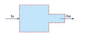 FIGURE P15-46C
Want to see the full answer?
Check out a sample textbook solution
Chapter 15 Solutions
Fluid Mechanics: Fundamentals and Applications


- 100 As a spring is heated, its spring constant decreases. Suppose the spring is heated and then cooled so that the spring constant at time t is k(t) = t sin N/m. If the mass-spring system has mass m = 2 kg and a damping constant b = 1 N-sec/m with initial conditions x(0) = 6 m and x'(0) = -5 m/sec and it is subjected to the harmonic external force f(t) = 100 cos 3t N. Find at least the first four nonzero terms in a power series expansion about t = 0, i.e. Maclaurin series expansion, for the displacement: Analytically (hand calculations)arrow_forwardthis is answer to a vibrations question. in the last part it states an assumption of x2, im not sure where this assumption comes from. an answer would be greatly appreciatedarrow_forwardPlease answer with the sketches.arrow_forward
- The beam is made of elastic perfectly plastic material. Determine the shape factor for the cross section of the beam (Figure Q3). [Take σy = 250 MPa, yNA = 110.94 mm, I = 78.08 x 106 mm²] y 25 mm 75 mm I 25 mm 200 mm 25 mm 125 Figure Q3arrow_forwardA beam of the cross section shown in Figure Q3 is made of a steel that is assumed to be elastic- perfectectly plastic material with E = 200 GPa and σy = 240 MPa. Determine: i. The shape factor of the cross section ii. The bending moment at which the plastic zones at the top and bottom of the bar are 30 mm thick. 15 mm 30 mm 15 mm 30 mm 30 mm 30 mmarrow_forwardA torque of magnitude T = 12 kNm is applied to the end of a tank containing compressed air under a pressure of 8 MPa (Figure Q1). The tank has a 180 mm inner diameter and a 12 mm wall thickness. As a result of several tensile tests, it has been found that tensile yeild strength is σy = 250 MPa for thr grade of steel used. Determine the factor of safety with respect to yeild, using: (a) The maximum shearing stress theory (b) The maximum distortion energy theory T Figure Q1arrow_forward
- An external pressure of 12 MPa is applied to a closed-end thick cylinder of internal diameter 150 mm and external diameter 300 mm. If the maximum hoop stress on the inner surface of the cylinder is limited to 30 MPa: (a) What maximum internal pressure can be applied to the cylinder? (b) Sketch the variation of hoop and radial stresses across the cylinder wall. (c) What will be the change in the outside diameter when the above pressure is applied? [Take E = 207 GPa and v = 0.29]arrow_forwardso A 4 I need a detailed drawing with explanation し i need drawing in solution motion is as follows; 1- Dwell 45°. Plot the displacement diagram for a cam with flat follower of width 14 mm. The required 2- Rising 60 mm in 90° with Simple Harmonic Motion. 3- Dwell 90°. 4- Falling 60 mm for 90° with Simple Harmonic Motion. 5- Dwell 45°. cam is 50 mm. Then design the cam profile to give the above displacement diagram if the minimum circle diameter of the か ---2-125 750 x2.01 98Parrow_forwardFigure below shows a link mechanism in which the link OA rotates uniformly in an anticlockwise direction at 10 rad/s. the lengths of the various links are OA=75 mm, OB-150 mm, BC=150 mm, CD-300 mm. Determine for the position shown, the sliding velocity of D. A 45 B Space Diagram o NTS (Not-to-Scale) C Darrow_forward
- I need a detailed drawing with explanation so Solle 4 يكا Pax Pu + 96** motion is as follows; 1- Dwell 45°. Plot the displacement diagram for a cam with flat follower of width 14 mm. The required 2- Rising 60 mm in 90° with Simple Harmonic Motion. 3- Dwell 90°. 4- Falling 60 mm for 90° with Simple Harmonic Motion. 5- Dwell 45°. cam is 50 mm. Then design the cam profile to give the above displacement diagram if the minimum circle diameter of the 55 ---20125 750 X 2.01 1989arrow_forwardAshaft fitted with a flywheel rotates at 300 rpm. and drives a machine. The torque required to drive the machine varies in a cyclic manner over a period of 2 revolutions. The torque drops from 20,000 Nm to 10,000 Nm uniformly during 90 degrees and remains constant for the following 180 degrees. It then rises uniformly to 35,000 Nm during the next 225 degrees and after that it drops to 20,000 in a uniform manner for 225 degrees, the cycle being repeated thereafter. Determine the power required to drive the machine and percentage fluctuation in speed, if the driving torque applied to the shaft is constant and the mass of the flywheel is 12 tonnes with radius of gyration of 500 mm. What is the maximum angular acceleration of the flywheel. 35,000 TNM 20,000 10,000 0 90 270 495 Crank angle 8 degrees 720arrow_forwardchanism shown in figure below, the crank OA rotates at 60 RPM counterclockwise. The velocity diagram is also drawn to scale (take dimensions from space diagram). Knowing that QCD is rigid plate, determine: a. Linear acceleration of slider at B, b. Angular acceleration of the links AC, plate CQD, and BD. D Space Diagram Scale 1:10 A ES a o,p,g b Velocity Diagram Scale 50 mm/(m/s) darrow_forward
 Elements Of ElectromagneticsMechanical EngineeringISBN:9780190698614Author:Sadiku, Matthew N. O.Publisher:Oxford University Press
 Mechanics of Materials (10th Edition)Mechanical EngineeringISBN:9780134319650Author:Russell C. HibbelerPublisher:PEARSON
 Thermodynamics: An Engineering ApproachMechanical EngineeringISBN:9781259822674Author:Yunus A. Cengel Dr., Michael A. BolesPublisher:McGraw-Hill Education
 Control Systems EngineeringMechanical EngineeringISBN:9781118170519Author:Norman S. NisePublisher:WILEY
 Mechanics of Materials (MindTap Course List)Mechanical EngineeringISBN:9781337093347Author:Barry J. Goodno, James M. GerePublisher:Cengage Learning
 Engineering Mechanics: StaticsMechanical EngineeringISBN:9781118807330Author:James L. Meriam, L. G. Kraige, J. N. BoltonPublisher:WILEY