
Mechanics of Materials, Student Value Edition (10th Edition)
10th Edition
ISBN: 9780134321189
Author: Russell C. Hibbeler
Publisher: PEARSON
expand_more
expand_more
format_list_bulleted
Concept explainers
Videos
Textbook Question
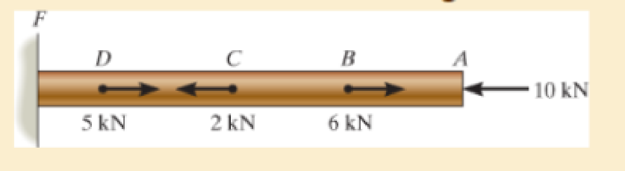
Chapter 1.5, Problem 1.3PP
Determine the largest internal normal force in the bar.
Expert Solution & Answer
Want to see the full answer?
Check out a sample textbook solution
Students have asked these similar questions
VIMA
1. Calculation
Calculate the DOF of the following mechanis
m
2
3
1
Please enter the answer
a) Determine state of stress at all points (a, b and c). These points are located on the exteriorsurface of the beam. Point a is located along the centreline of the beam, point b is 15mmfrom the centreline and point c is located on the edge of the beam. Present yourresults in a table and ensure that your sign convention is clearly shownb) Construct Mohrs circle at this point andcalculate the principal stresses and maximum in‐plane shear stress (τmax) at pointc. sketch the resulting state of stress at this point clearly indicating themagnitude of the stresses and any angles associated with the state of stress (principal ormaximum in‐plane shear).
Chapter 1 Solutions
Mechanics of Materials, Student Value Edition (10th Edition)
Ch. 1.2 - In each case, explain how to find the resultant...Ch. 1.2 - Determine the resultant internal normal force,...Ch. 1.2 - Determine the resultant internal normal force,...Ch. 1.2 - Determine the resultant internal normal force,...Ch. 1.2 - Determine the resultant internal normal force,...Ch. 1.2 - Determine the resultant internal normal force,...Ch. 1.2 - Determine the resultant internal normal force,...Ch. 1.2 - The shaft is supported by a smooth thrust bearing...Ch. 1.2 - Determine the resultant internal normal and shear...Ch. 1.2 - Determine the resultant internal loadings acting...
Ch. 1.2 - The shaft is supported by a smooth thrust bearing...Ch. 1.2 - Determine the resultant internal loadings acting...Ch. 1.2 - Determine the resultant internal loadings on the...Ch. 1.2 - Determine the resultant internal loadings at cross...Ch. 1.2 - The beam supports the distributed load shown....Ch. 1.2 - The beam supports the distributed load shown....Ch. 1.2 - The boom DF of the jib crane and the column DE...Ch. 1.2 - Determine the resultant internal loadings acting...Ch. 1.2 - Determine the resultant internal loadings acting...Ch. 1.2 - The blade of the hacksaw is subjected to a...Ch. 1.2 - The blade of the hacksaw is subjected to a...Ch. 1.2 - The beam supports the triangular distributed load...Ch. 1.2 - The beam supports the distributed load shown....Ch. 1.2 - The shaft is supported at its ends by two bearings...Ch. 1.2 - The shaft is supported at its ends by two bearings...Ch. 1.2 - The hand crank that is used in a press has the...Ch. 1.2 - Determine the resultant internal loadings acting...Ch. 1.2 - Determine the resultant internal loadings acting...Ch. 1.2 - The metal stud punch is subjected to a force of...Ch. 1.2 - Determine the resultant internal loadings acting...Ch. 1.2 - Determine the resultant internal loadings acting...Ch. 1.2 - Determine the resultant internal loadings acting...Ch. 1.2 - Determine the resultant internal loadings acting...Ch. 1.2 - The pipe has a mass of 12 kg/m. If it is fixed to...Ch. 1.2 - If the drill bit jams when the brace is subjected...Ch. 1.2 - The curved rod AD of radius r has a weight per...Ch. 1.2 - A differential element taken from a curved bar is...Ch. 1.5 - In each case, determine the largest internal shear...Ch. 1.5 - Determine the largest internal normal force in the...Ch. 1.5 - Determine the internal normal force at section A...Ch. 1.5 - The lever is held to the fixed shaft using the pin...Ch. 1.5 - The single-V butt joint transmits the force of 5...Ch. 1.5 - The uniform beam is supported by two rods AB and...Ch. 1.5 - Determine the average normal stress on the cross...Ch. 1.5 - Determine the average normal stress on the cross...Ch. 1.5 - If the 600-kN force acts through the centroid of...Ch. 1.5 - Determine the average normal stress at points A,...Ch. 1.5 - Determine the average normal stress in rod AB if...Ch. 1.5 - The supporting wheel on a scaffold is held in...Ch. 1.5 - Determine the largest intensity w of the uniform...Ch. 1.5 - The bar has a cross-sectional area A and is...Ch. 1.5 - The small block has a thickness of 0.5 in. If the...Ch. 1.5 - If the material fails when the average normal...Ch. 1.5 - If the block is subjected to a centrally applied...Ch. 1.5 - The plate has a width of 0.5 m. If the stress...Ch. 1.5 - The board is subjected to a tensile force of 200...Ch. 1.5 - The boom has a uniform weight of 600 lb and is...Ch. 1.5 - Determine the average normal stress in each of the...Ch. 1.5 - If the average normal stress in each of the...Ch. 1.5 - Determine the maximum average shear stress in pin...Ch. 1.5 - If P=5 kN, determine the average shear stress in...Ch. 1.5 - Determine the maximum magnitude P of the loads the...Ch. 1.5 - The column is made of concrete having a density of...Ch. 1.5 - The beam is supported by two rods AB and CD that...Ch. 1.5 - The beam is supported by two rods AB and CD that...Ch. 1.5 - If P = 15 kN, determine the average shear stress...Ch. 1.5 - The railcar docklight is supported by the...Ch. 1.5 - The plastic block is subjected to an axial...Ch. 1.5 - The two steel members are joined together using a...Ch. 1.5 - The bar has a cross-sectional area of 400(106) m2....Ch. 1.5 - The bar has a cross-sectional area of 400(106) m2....Ch. 1.5 - The two members used in the construction of an...Ch. 1.5 - The 2-Mg concrete pipe has a center of mass at...Ch. 1.5 - The 2-Mg concrete pipe has a center of mass at...Ch. 1.5 - The pier is made of material having a specific...Ch. 1.5 - Rods AB and BC have diameters of 4 mm and 6 mm,...Ch. 1.5 - The uniform bar, having a cross-sectional area of...Ch. 1.5 - The bar has a cross-sectional area of 400(106) m2....Ch. 1.5 - The bar has a cross-sectional area of 400(106) m2....Ch. 1.5 - The prismatic bar has a cross-sectional area A. If...Ch. 1.5 - The prismatic bar has a cross-sectional area A. If...Ch. 1.5 - The bars of the truss each have a cross-sectional...Ch. 1.5 - The bars of the truss each have a cross-sectional...Ch. 1.5 - Determine the largest load P that can be applied...Ch. 1.5 - Determine the greatest constant angular velocity ...Ch. 1.5 - The radius of the pedestal is defined by r =...Ch. 1.7 - Rods AC and BC are used to suspend the 200-kg...Ch. 1.7 - If it is subjected to double shear, determine the...Ch. 1.7 - Determine the maximum average shear stress...Ch. 1.7 - If each of the three nails has a diameter of 4 mm...Ch. 1.7 - The strut is glued to the horizontal member at...Ch. 1.7 - Determine the maximum average shear stress...Ch. 1.7 - If the eyebolt is made of a material having a...Ch. 1.7 - If the bar assembly is made of a material having a...Ch. 1.7 - Determine the maximum force P that can be applied...Ch. 1.7 - The pin is made of a material having a failure...Ch. 1.7 - If the bolt head and the supporting bracket are...Ch. 1.7 - Six nails are used to hold the hanger at A against...Ch. 1.7 - If A and B are both made of wood and are 38 in....Ch. 1.7 - Prob. 1.70PCh. 1.7 - The connection is made using a bolt and nut and...Ch. 1.7 - The tension member is fastened together using two...Ch. 1.7 - The steel swivel bushing in the elevator control...Ch. 1.7 - The spring mechanism is used as a shock absorber...Ch. 1.7 - Determine the size of square bearing plates A and...Ch. 1.7 - Determine the maximum load P that can be applied...Ch. 1.7 - Determine the required diameter of the pins at A...Ch. 1.7 - If the allowable tensile stress for wires AB and...Ch. 1.7 - If the allowable tensile stress for wires AB and...Ch. 1.7 - The cotter is used to hold the two rods together....Ch. 1.7 - Determine the required diameter of the pins at A...Ch. 1.7 - The steel pipe is supported on the circular base...Ch. 1.7 - The boom is supported by the winch cable that has...Ch. 1.7 - The boom is supported by the winch cable that has...Ch. 1.7 - The assembly consists of three disks A, B, and C...Ch. 1.7 - The two aluminum rods support the vertical force...Ch. 1.7 - The two aluminum rods AB and AC have diameters of...Ch. 1.7 - Determine the required minimum thickness t of...Ch. 1.7 - Determine the maximum allowable load P that can be...Ch. 1.7 - The compound wooden beam is connected together by...Ch. 1.7 - The hanger is supported using the rectangular pin....Ch. 1.7 - The hanger is supported using the rectangular pin....Ch. 1.7 - The rods AB and CD are made of steel. Determine...Ch. 1.7 - The aluminum bracket A is used to support the...Ch. 1.7 - If the allowable tensile stress for the bar is...Ch. 1.7 - The bar is connected to the support using a pin...Ch. 1 - The beam AB is pin supported at A and supported by...Ch. 1 - The long bolt passes through the 30-mm-thick...Ch. 1 - Determine the required thickness of member BC to...Ch. 1 - The circular punch B exerts a force of 2 kN on the...Ch. 1 - Determine the average punching shear stress the...Ch. 1 - The 150 mm by 150 mm block of aluminum supports a...Ch. 1 - The yoke-and-rod connection is subjected to a...Ch. 1 - The cable has a specific weight (weight/volume)...
Knowledge Booster


Learn more about
Need a deep-dive on the concept behind this application? Look no further. Learn more about this topic, mechanical-engineering and related others by exploring similar questions and additional content below.Similar questions
- parts e,f,garrow_forwardFigure 9-6 9-49 An aluminum alloy plate with dimensions 20 cm x 10 cm × 2 cm needs to be cast with a secondary dendrite arm spacing of 10-2 cm (refer to Figure 9-6). What mold constant B is required (assume n = 2 )? Secondary dendrite arm spacing (cm) - 10-1 10-2 10-3 10 41 0.1 1 Copper Zinc alloys Aluminum alloys 10 100 1,000 10,000 100,000 Solidification time (s)arrow_forward9-72 Figure 9-29 shows a cylindrical riser attached to a casting. Compare the solidification times for each casting section and the riser and determine whether the riser will be effective. Figure 9-29 Т 3 6 3 8 3 6 Details A diagram shows the step-block casting. A cylinder of height "7" and diameter "3" is kept on a platform consisting of 2 steps. The width of the second step of the platform is labeled as "3". The horizontal length of the first step is labeled as "6." The horizontal length, width and height of the first step are labeled "6", "8" and "3".arrow_forward
- 6/94 Determine the minimum coefficient of static friction for which the bar can be in static equilibrium in the config- uration shown. The bar is uniform and the fixed peg at C is small. Neglect friction at B. A L PROBLEM 6/94 B L 22arrow_forwardQ2. For the following situation, estimate the minimum required compressive strength of 20/40 proppant. If intermediate-strength proppant is used, estimate the permeability of the proppant pack: Formation depth: 10,000 ft Overburden density: 165lbm/ft3 Poison’s ratio: 0.25 Biot constant: 0.7 Reservoir pressure: 6,500 psi Production drawdown: 2,000 and 4,000 psiarrow_forwardA 3-in.-radius drum is rigidly attached to a 5-in.-radius drum as shown. One of the drums rolls without sliding on the surface shown, and a cord is wound around the other drum. Knowing that at the instant shown. point A has a velocity of 4.875 in./sin./s and an acceleration of 15.50 in./s2in./s2 , both directed to the right, determine the accelerations of points A, B, and C of the drums. The cord is wound around the 3 inch radius drum. Point B is at the bottom of the 5 inch radius drum. Point A is at the bottom of the 3 inch radius drum. Point C is on the right edge of the 5 inch radius drum. The accelerations of point B is______ in./s2 . The accelerations of point A is ______ in./s2 ______ ⦨ °. at what angle/direction The accelerations of point C is______ in./s2 ______ ⦪ °. at what angle/direction?arrow_forward
- A total volume of mud is 1,000 bbls that has a mud weight of 9.1 ppg. Calculate the volumefractions of water, Bentonite, and the weight of Bentonite used. Density of powder Bentonite is 156 lbm/ft3arrow_forwardA 3-in.-radius drum is rigidly attached to a 5-in.-radius drum as shown. One of the drums rolls without sliding on the surface shown, and a cord is wound around the other drum. Knowing that at the instant shown. point A has a velocity of 4.875 in./sin./s and an acceleration of 15.50 in./s2in./s2 , both directed to the right, determine the accelerations of points A, B, and C of the drums. The cord is wound around the 3 inch radius drum. Point B is at the bottom of the 5 inch radius drum. Point A is at the bottom of the 3 inch radius drum. Point C is on the right edge of the 5 inch radius drum. The accelerations of point B is ______ in./s2 The accelerations of point A is ______ in./s2 _____⦨ °. The accelerations of point C is _______ in./s2 ____ ⦪ °.arrow_forwardThe average heat transfer coefficent for airflow over an odd shaped body is to be determined by mass transfer measurements and using the Chilton-Colburn analogy btwn heat and mass transfer. The experiemnt is conducted by blowing dry air at 1 atm at a free-stream velocity of 2 m/s over a body covered with a layer of naphthalene. The surface area of the body is .75 m^2, and it is observed that 100 g of maphthalene has sublimated in 45 min. During the experiemnt, both the body and the air were kep at 25oC, at which the vapor pressure and mass diffusivity of naphthalene are 11 Pa and Dab=0.61*10^-5 m^2/s respectively. Determine the heat transfer coefficent under the same flow conditions over the same geometry.arrow_forward
- Auto Controls Design a PID controller for thefollowing system so that the modified system satisfies the followingspecifications : 1. settling time ,ts = 1.96 s and % Overshoot Mp = 70.7 % Assume a non-dominant pole at s = -15 to solve the problem The plot the compensated andThen plot the uncompensated system in MATLAB. what can you see from the plot ? what is your observation ?arrow_forwardAuto Controls The figure is a schematic diagram of an aircraft elevator control system. The input to the systemin the deflection angle of the control lever , and the output is the elevator angle phi.show that for each angle theta of the control lever ,there is a corresponding elevator angle phi. Then find Y(s)/theta(s) and simplify the resulting transfer function . Also note from the diagram that y and phi is relatedarrow_forwardFresh water is planned to be pumped in a certain pipe at constant pumping rate of 6.5 gpm. If water density and viscosity are 8.34 ppg and 1.0 cp, what is the minimum pipe inside diameter that make the fluid flow behave as turbulent flow?arrow_forward
arrow_back_ios
SEE MORE QUESTIONS
arrow_forward_ios
Recommended textbooks for you
 International Edition---engineering Mechanics: St...Mechanical EngineeringISBN:9781305501607Author:Andrew Pytel And Jaan KiusalaasPublisher:CENGAGE L
International Edition---engineering Mechanics: St...
Mechanical Engineering
ISBN:9781305501607
Author:Andrew Pytel And Jaan Kiusalaas
Publisher:CENGAGE L
Engineering Basics - Statics & Forces in Equilibrium; Author: Solid Solutions - Professional Design Solutions;https://www.youtube.com/watch?v=dQBvQ2hJZFg;License: Standard YouTube License, CC-BY