Mechanics of Materials
9th Edition
ISBN: 9780133254426
Author: Russell C. Hibbeler
Publisher: Prentice Hall
expand_more
expand_more
format_list_bulleted
Textbook Question
Chapter 1.5, Problem 1.2PP
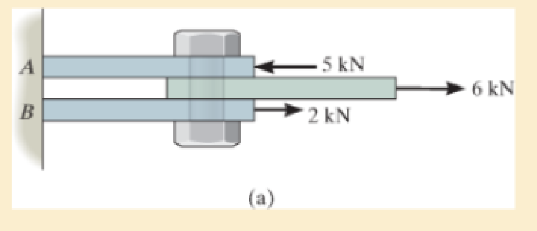
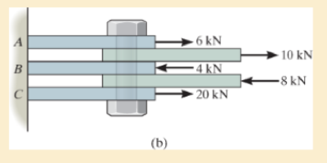
In each case, determine the largest internal shear force resisted by the bolt. Include all necessary free-body diagrams.


Expert Solution & Answer
Trending nowThis is a popular solution!
Learn your wayIncludes step-by-step video

schedule03:12
Students have asked these similar questions
6.3 Contamination of vegetable oil
Vegetable oil is used in a food processing factory to prepare instant breadcrumbs. A stirred tank is used to hold the oil.
During operation of the breadcrumb process, oil is pumped from the tank at a rate of 4.8 1 h-¹. At 8 PM during the
night shift, the tank is mistakenly connected to a drum of cod liver oil, which is then pumped into the tank. The volume
of vegetable oil in the tank at 8 PM is 60 1.
(a) If the flow rate of cod liver oil into the tank is 7.5 1h-1 and the tank has a maximum capacity of 100 1, will the tank
overflow before the factory manager arrives at 9 AM? Assume that the density of both oils is the same.
(b) If cod liver oil is pumped into the tank at a rate of 4.8 1 h 1 instead of 7.5 1 h−1, what is the composition of oil in
the tank at midnight?
6.1 Dilution of sewage
In a sewage treatment plant, a large concrete tank initially contains 440,000 litres of liquid and 10,000 kg of fine
suspended solids. To flush this material out of the tank, water is pumped into the vessel at a rate of 40,000 1 h −1.
Liquid containing solids leaves at the same rate. Estimate the concentration of suspended solids in the tank at the end of
5 h. State your assumptions.
6.13 Heating glycerol solution
An adiabatic stirred tank is used to heat 100 kg of a 45% glycerol solution in water. An electrical coil delivers 2.5 kW
of power to the tank; 88% of the energy delivered by the coil goes into heating the vessel contents. The glycerol
solution is initially at 15°C.
(a) Write a differential equation for the energy balance.
(b) Integrate the equation to obtain an expression for temperature as a function of time.
(c) Assuming glycerol and water form an ideal solution, how long will the solution take to reach 90°C?
Chapter 1 Solutions
Mechanics of Materials
Ch. 1.2 - In each case, explain how to find the resultant...Ch. 1.2 - Determine the resultant internal normal force,...Ch. 1.2 - Determine the resultant internal normal force,...Ch. 1.2 - Determine the resultant internal normal force,...Ch. 1.2 - Determine the resultant internal normal force,...Ch. 1.2 - Determine the resultant internal normal force,...Ch. 1.2 - Determine the resultant internal normal force,...Ch. 1.2 - The shaft is supported by a smooth thrust bearing...Ch. 1.2 - Determine the resultant internal normal and shear...Ch. 1.2 - 1-3. The beam AB is fixed to the wall and has a...
Ch. 1.2 - The shaft is supported by a smooth thrust bearing...Ch. 1.2 - 1-5. Determine the resultant internal loadings in...Ch. 1.2 - 1-6. Determine the normal force, shear force, and...Ch. 1.2 - 1-7. The cable will fail when subjected to a...Ch. 1.2 - *1-8. Determine the resultant internal loadings on...Ch. 1.2 - 1-9. Determine the resultant internal loadings on...Ch. 1.2 - The boom DF of the jib crane and the column DE...Ch. 1.2 - 1-11. The forearm and biceps support the 2-kg load...Ch. 1.2 - *1-12. The serving tray T used on an airplane is...Ch. 1.2 - The blade of the hacksaw is subjected to a...Ch. 1.2 - The blade of the hacksaw is subjected to a...Ch. 1.2 - 1-15. A 150-lb bucket is suspended from a cable on...Ch. 1.2 - *1-16. A 150-lb bucket is suspended from a cable...Ch. 1.2 - 1-17. Determine resultant internal loadings acting...Ch. 1.2 - Prob. 1.18PCh. 1.2 - Prob. 1.19PCh. 1.2 - Prob. 1.20PCh. 1.2 - Prob. 1.21PCh. 1.2 - The metal stud punch is subjected to a force of...Ch. 1.2 - Determine the resultant internal loadings acting...Ch. 1.2 - Prob. 1.24PCh. 1.2 - 1-25. Determine the resultant internal loading...Ch. 1.2 - 1-26. The shaft is supported at its ends by two...Ch. 1.2 - 1-27. The pipe assembly is subjected to a force of...Ch. 1.2 - If the drill bit jams when the brace is subjected...Ch. 1.2 - 1-29. The curved rod AD of radius r has a weight...Ch. 1.2 - A differential element taken from a curved bar is...Ch. 1.5 - In each case, determine the largest internal shear...Ch. 1.5 - Determine the largest internal normal force in the...Ch. 1.5 - Determine the internal normal force at section A...Ch. 1.5 - Prob. 1.5PPCh. 1.5 - The single-V butt joint transmits the force of 5...Ch. 1.5 - The uniform beam is supported by two rods AB and...Ch. 1.5 - Determine the average normal stress on the cross...Ch. 1.5 - Determine the average normal stress on the cross...Ch. 1.5 - If the 600-kN force acts through the centroid of...Ch. 1.5 - Determine the average normal stress at points A,...Ch. 1.5 - Determine the average normal stress in rod AB if...Ch. 1.5 - The supporting wheel on a scaffold is held in...Ch. 1.5 - Prob. 1.32PCh. 1.5 - The bar has a cross-sectional area A and is...Ch. 1.5 - 1-34. The built-up shaft consists of a pipe AB and...Ch. 1.5 - Prob. 1.35PCh. 1.5 - Prob. 1.36PCh. 1.5 - The plate has a width of 0.5 m. If the stress...Ch. 1.5 - The two members used in the construction of an...Ch. 1.5 - Prob. 1.39PCh. 1.5 - Determine the average normal stress in each of the...Ch. 1.5 - If the average normal stress in each of the...Ch. 1.5 - Determine the maximum average shear stress in pin...Ch. 1.5 - 1-43. The 150-kg bucket is suspended from end E of...Ch. 1.5 - *1-44. The 150-kg bucket is suspended from end E...Ch. 1.5 - Prob. 1.45PCh. 1.5 - 1-46. The 20-kg chandelier is suspended from the...Ch. 1.5 - Prob. 1.47PCh. 1.5 - If P = 15 kN, determine the average shear stress...Ch. 1.5 - 1-49. The joint is subjected to the axial member...Ch. 1.5 - Prob. 1.50PCh. 1.5 - Prob. 1.51PCh. 1.5 - Prob. 1.52PCh. 1.5 - Prob. 1.53PCh. 1.5 - Prob. 1.54PCh. 1.5 - The 2-Mg concrete pipe has a center of mass at...Ch. 1.5 - The 2-Mg concrete pipe has a center of mass at...Ch. 1.5 - Prob. 1.57PCh. 1.5 - Prob. 1.58PCh. 1.5 - 1-59. The jib crane is pinned at A and supports a...Ch. 1.5 - *1-60. If the shaft is subjected to an axial force...Ch. 1.5 - Prob. 1.61PCh. 1.5 - Prob. 1.62PCh. 1.5 - Prob. 1.63PCh. 1.5 - *1-64. A vertical force of P = 1500 N is applied...Ch. 1.5 - Prob. 1.65PCh. 1.5 - Determine the largest load P that can be applied...Ch. 1.5 - Prob. 1.67PCh. 1.5 - Prob. 1.68PCh. 1.7 - Rods AC and BC are used to suspend the 200-kg...Ch. 1.7 - If it is subjected to double shear, determine the...Ch. 1.7 - Determine the maximum average shear stress...Ch. 1.7 - If each of the three nails has a diameter of 4 mm...Ch. 1.7 - The strut is glued to the horizontal member at...Ch. 1.7 - Determine the maximum average shear stress...Ch. 1.7 - If the eyebolt is made of a material having a...Ch. 1.7 - If the bar assembly is made of a material having a...Ch. 1.7 - Determine the maximum force P that can be applied...Ch. 1.7 - The pin is made of a material having a failure...Ch. 1.7 - If the bolt head and the supporting bracket are...Ch. 1.7 - Six nails are used to hold the hanger at A against...Ch. 1.7 - If A and B are both made of wood and are 38 in....Ch. 1.7 - Prob. 1.70PCh. 1.7 - Prob. 1.71PCh. 1.7 - Prob. 1.72PCh. 1.7 - The steel swivel bushing in the elevator control...Ch. 1.7 - 1-74. Member B is subjected to a compressive force...Ch. 1.7 - Prob. 1.75PCh. 1.7 - Prob. 1.76PCh. 1.7 - The tension member is fastened together using two...Ch. 1.7 - 1-78. The 50-kg flowerpot is suspended from wires...Ch. 1.7 - 1-79. The 50-kg flowerpot is suspended from wires...Ch. 1.7 - *1–80. The thrust bearing consists of a circular...Ch. 1.7 - 1-81. The steel pipe is supported on the circular...Ch. 1.7 - The steel pipe is supported on the circular base...Ch. 1.7 - 1-83. The 60 mm × 60 mm oak post is supported on...Ch. 1.7 - *1-84. The frame is subjected to the load of 4 kN...Ch. 1.7 - Prob. 1.85PCh. 1.7 - The two aluminum rods support the vertical force...Ch. 1.7 - The two aluminum rods AB and AC have diameters of...Ch. 1.7 - The compound wooden beam is connected together by...Ch. 1.7 - Determine the required minimum thickness t of...Ch. 1.7 - Determine the maximum allowable load P that can be...Ch. 1.7 - Prob. 1.91PCh. 1.7 - *1-92. If the allowable hearing stress for the...Ch. 1.7 - The rods AB and CD are made of steel. Determine...Ch. 1.7 - The aluminum bracket A is used to support the...Ch. 1.7 - Prob. 1.95PCh. 1.7 - *1-96. The pin support A and roller support B of...Ch. 1 - The beam AB is pin supported at A and supported by...Ch. 1 - The long bolt passes through the 30-mm-thick...Ch. 1 - Determine the required thickness of member BC to...Ch. 1 - The circular punch B exerts a force of 2 kN on the...Ch. 1 - Determine the average punching shear stress the...Ch. 1 - The 150 mm by 150 mm block of aluminum supports a...Ch. 1 - The yoke-and-rod connection is subjected to a...Ch. 1 - The cable has a specific weight (weight/volume)...
Additional Engineering Textbook Solutions
Find more solutions based on key concepts
A class member function that uses, but does not change, the value of a member variable is called a(n) ________ ...
Starting Out with C++: Early Objects (9th Edition)
The data shown in the following graph was collected during testing of an electromagnetic mass driver. The energ...
Thinking Like an Engineer: An Active Learning Approach (4th Edition)
Determine the magnitude of F2 which will cause the reaction C, at the bearing C to be equal to zero. The bearin...
INTERNATIONAL EDITION---Engineering Mechanics: Statics, 14th edition (SI unit)
Hot Dog Cookout Calculator Assume hot dogs come in packages of 10, and hot dog buns come in packages of 8. Writ...
Starting Out with Python (4th Edition)
Given that y=ax3+7, which of the following are correct Java statements for this equations? int y = a x x (x +...
Java How to Program, Early Objects (11th Edition) (Deitel: How to Program)
Assume a telephone signal travels through a cable at two-thirds the speed of light. How long does it take the s...
Electric Circuits. (11th Edition)
Knowledge Booster
Learn more about
Need a deep-dive on the concept behind this application? Look no further. Learn more about this topic, mechanical-engineering and related others by exploring similar questions and additional content below.Similar questions
- please find Ix and Iy in mm4arrow_forwardHomework#7arrow_forwardComputing Angles of Rotation and Angles of Tilt In each of the following problems, the axis of a hole is shown in a rectangular solid. In order to position the hole axis for drilling, the angle of rotation and the angle of tilt must be determined. Compute angles to the nearer minute in triangles with customary unit sides. Compute angles to the nearer hundredth degree in triangles with metric unit sides. a. Compute the angle of rotation, R. b. Compute the angle of tilt, T. 7. Given: H= 2.600 in. L = 2.400 in. a. W= 1.900 in. 8. Given: H= 55.00 mm b. Use this figure for #7 and #8. AXIS OF HOLE L 48.00 mm W= 30.00 mm H a. b. 9. Given: H = 4.750 in. L = 4.000 in. W= 3.750 in. a. 10. Given: H=42.00 mm b. L37.00 mm W = 32.00 mm a. b. 11. Given: H = 0.970 in. L = 0.860 in. W= 0.750 in. a. 12. Given: H= 22.00 mm L 18.00 mm = W = 15.00 mm a. b. Use this figure for #9 and #10. ZR AXIS OF HOLE Use this figure for #11 and #12. H b. L AXIS OF HOLE Tarrow_forward
- This is a tilt and rotation question. Here are notes attached for reference. I prefer handwritten solutions. ONLY UPLOAD A SOLUTION IF YOU ARE SURE ABOUT THE ANSWER PLEASE. I prefer handwritten solutions.arrow_forwardConsider a constant area semi-infinite fin of a circular cross section of radius r. and thermal conductivity k. The base is maintained at T. and the surface of the fin exchanges heat by convection to an ambient fluid at T with a heat transfer coefficient h. It is desired to increase the heat transfer from the fin. The following suggestions are made: (i) doubling k, (ii) doubling ro, (iii) doubling h. Which suggestion will bring about the largest increase in heat transfer? To x h, T C A h, Tarrow_forwardA 20 cm long 304 stainless steel bar is initially at 18°C. One end of the bar is suddenly maintained at 100°C. Assuming that your finger can tolerate a 60°C temperature, what is the longest time you are willing to wait before you touch the other end? Be on the safe side and select a conservative model. h,T oil bath glass ballarrow_forward
arrow_back_ios
SEE MORE QUESTIONS
arrow_forward_ios
Recommended textbooks for you
 International Edition---engineering Mechanics: St...Mechanical EngineeringISBN:9781305501607Author:Andrew Pytel And Jaan KiusalaasPublisher:CENGAGE L
 Mechanics of Materials (MindTap Course List)Mechanical EngineeringISBN:9781337093347Author:Barry J. Goodno, James M. GerePublisher:Cengage Learning

International Edition---engineering Mechanics: St...
Mechanical Engineering
ISBN:9781305501607
Author:Andrew Pytel And Jaan Kiusalaas
Publisher:CENGAGE L

Mechanics of Materials (MindTap Course List)
Mechanical Engineering
ISBN:9781337093347
Author:Barry J. Goodno, James M. Gere
Publisher:Cengage Learning
Everything About TRANSVERSE SHEAR in 10 Minutes!! - Mechanics of Materials; Author: Less Boring Lectures;https://www.youtube.com/watch?v=4x0E9yvzfCM;License: Standard Youtube License