
Videos
Atmospheric air enters an air-conditioning system at 30°C and 70 percent relative humidity with a volume flow rate of 4 m3/min and is cooled to 20°C and 20 percent relative humidity at a pressure of 1 atm. The system uses refrigerant-134a as the cooling fluid that enters the cooling section at 350 kPa with a quality of 20 percent and leaves as a saturated vapor. Show the process on the psychrometric chart. What is the heat transfer from the air to the cooling coils, in kW? If any water is condensed from the air, how much water will be condensed from the atmospheric air per min? Determine the mass flow rate of the refrigerant, in kg/min.
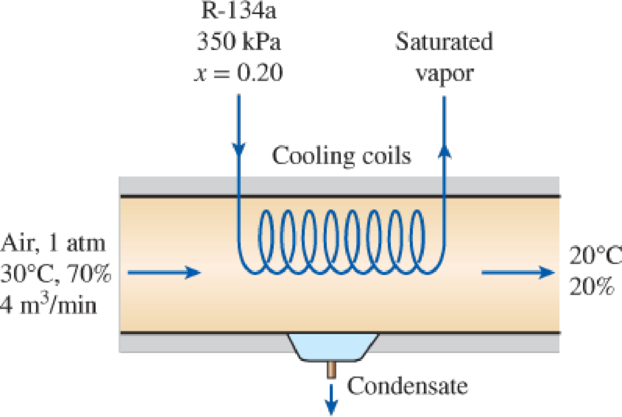
FIGURE P14–132
Show the process on the psychrometric chart; find the heat transfer from the air to the cooling coils, how much water will be condensed from the atmospheric air per min and the mass flow rate of the refrigerant.
Answer to Problem 132RP
The process on the psychrometric chart is shown below in Figure (1), the heat transfer from the air to the cooling coils is
Explanation of Solution
As the process is a steady flow and thus the mass flow rate of dry air remains constant during the entire process.
Here, the mass flow rate of air at inlet is
Express the mass flow rate of dry air.
Here, volume flow rate at inlet is
Express the mass flow rate of vapor at inlet.
Here, specific humidity at state 1 is
Express the mass flow rate of vapor at exit.
Here, specific humidity at state 2 is
Express the rate of condensation of water.
Express the enthalpy of condensate water.
Here, enthalpy of saturation liquid at temperature of
Express the rate required heat transfer rate from the atmospheric air to the evaporator fluid from an energy balance on the control volume.
Here, enthalpy at state 1 and 2 is
Express enthalpy of refrigerant at inlet.
Here, quality of refrigerant at inlet is
Express enthalpy of refrigerant at exit.
Here, quality of refrigerant at exit is
Express the mass flow rate of the refrigerant.
Here, enthalpy of refrigerant at inlet and exit is
Conclusion:
Show the psychrometric diagram as in Figure (1).
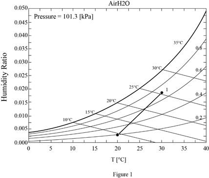
Hence, the psychrometric diagram is shown in Figure (1).
Refer Figure A-31, “psychometric chart at
Refer Figure A-31, “psychometric chart at
Substitute
Substitute
Substitute
Substitute
Hence, the amount of water condensed from the atmospheric air per min is
Refer Table A-4, “saturated water-temperature table”, and write the enthalpy of condensate water at temperature of
Here, enthalpy of saturation liquid is
Substitute
Substitute
Hence, the heat transfer from the air to the cooling coils is
Refer Table A-12, saturated refrigerant-134a-presure table”, and write enthalpy of saturation liquid at pressure of
Write the formula of interpolation method of two variables.
Here, the variables denote by x and y pressure and enthalpy of saturation liquid respectively.
Show the enthalpy of saturation liquid corresponding to pressure as in Table (1).
|
Pressure |
Enthalpy of saturation liquid |
| 320 | 55.14 |
| 350 | |
| 360 | 59.70 |
Substitute
Thus, the enthalpy of saturation liquid at pressure of
Refer Table A-12, saturated refrigerant-134a-presure table”, and write enthalpy of saturation vapor at pressure of
Show the enthalpy of saturation vapor corresponding to pressure as in Table (2).
|
Pressure |
Enthalpy of saturation liquid |
| 320 | 251.93 |
| 350 | |
| 360 | 253.86 |
Use excels and tabulates the values form Table (2) in Equation (X) to get,
Substitute
Substitute
Substitute
Hence, the mass flow rate of the refrigerant is
Want to see more full solutions like this?
Chapter 14 Solutions
THERMODYNAMICS LLF W/ CONNECT ACCESS


- Please do not use any AI tools to solve this question. I need a fully manual, step-by-step solution with clear explanations, as if it were done by a human tutor. No AI-generated responses, please.arrow_forwardPlease do not use any AI tools to solve this question. I need a fully manual, step-by-step solution with clear explanations, as if it were done by a human tutor. No AI-generated responses, please.arrow_forwardThis is an old practice exam. Fce = 110lb and FBCD = 62 lb but whyarrow_forward
- Quiz/An eccentrically loaded bracket is welded to the support as shown in Figure below. The load is static. The weld size for weld w1 is h1 = 4mm, for w2 h2 = 6mm, and for w3 is h3 =6.5 mm. Determine the safety factor (S.f) for the welds. F=29 kN. Use an AWS Electrode type (E100xx). 163 mm S 133 mm 140 mm Please solve the question above I solved the question but I'm sure the answer is wrong the link : https://drive.google.com/file/d/1w5UD2EPDiaKSx3W33aj Rv0olChuXtrQx/view?usp=sharingarrow_forwardQ2: (15 Marks) A water-LiBr vapor absorption system incorporates a heat exchanger as shown in the figure. The temperatures of the evaporator, the absorber, the condenser, and the generator are 10°C, 25°C, 40°C, and 100°C respectively. The strong liquid leaving the pump is heated to 50°C in the heat exchanger. The refrigerant flow rate through the condenser is 0.12 kg/s. Calculate (i) the heat rejected in the absorber, and (ii) the COP of the cycle. Yo 8 XE-V lo 9 Pc 7 condenser 5 Qgen PG 100 Qabs Pe evaporator PRV 6 PA 10 3 generator heat exchanger 2 pump 185 absorberarrow_forwardQ5:(? Design the duct system of the figure below by using the balanced pressure method. The velocity in the duct attached to the AHU must not exceed 5m/s. The pressure loss for each diffuser is equal to 10Pa. 100CFM 100CFM 100CFM ☑ ☑ 40m AHU -16m- 8m- -12m- 57m 250CFM 40m -14m- 26m 36m ☑ 250CFMarrow_forward
- A mass of ideal gas in a closed piston-cylinder system expands from 427 °C and 16 bar following the process law, pv1.36 = Constant (p times v to the power of 1.36 equals to a constant). For the gas, initial : final pressure ratio is 4:1 and the initial gas volume is 0.14 m³. The specific heat of the gas at constant pressure, Cp = 0.987 kJ/kg-K and the specific gas constant, R = 0.267 kJ/kg.K. Determine the change in total internal energy in the gas during the expansion. Enter your numerical answer in the answer box below in KILO JOULES (not in Joules) but do not enter the units. (There is no expected number of decimal points or significant figures).arrow_forwardmy ID# 016948724. Please solve this problem step by steparrow_forwardMy ID# 016948724 please find the forces for Fx=0: fy=0: fz=0: please help me to solve this problem step by steparrow_forward
- My ID# 016948724 please solve the proble step by step find the forces fx=o: fy=0; fz=0; and find shear moment and the bending moment diagran please draw the diagram for the shear and bending momentarrow_forwardMy ID#016948724. Please help me to find the moment of inertia lx ly are a please show to solve step by stepsarrow_forwardplease solve this problem step by steparrow_forward
 Refrigeration and Air Conditioning Technology (Mi...Mechanical EngineeringISBN:9781305578296Author:John Tomczyk, Eugene Silberstein, Bill Whitman, Bill JohnsonPublisher:Cengage Learning
 Principles of Heat Transfer (Activate Learning wi...Mechanical EngineeringISBN:9781305387102Author:Kreith, Frank; Manglik, Raj M.Publisher:Cengage Learning