
MECHANICS OF MATERIALS
11th Edition
ISBN: 9780137605521
Author: HIBBELER
Publisher: RENT PEARS
expand_more
expand_more
format_list_bulleted
Concept explainers
Videos
Textbook Question
Chapter 14, Problem 9RP
El is constant. Use the method of virtual work.
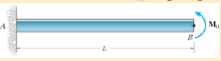
R14-9/10
Expert Solution & Answer
Want to see the full answer?
Check out a sample textbook solution
Students have asked these similar questions
using the theorem of three moments, find all the moments, I need concise calculations only
Practise question need help on
Can you show explaination and working. The answer from the text book is Q=5.03 X 10^-3
Chapter 14 Solutions
MECHANICS OF MATERIALS
Ch. 14.2 - A material is subjected to a general state of...Ch. 14.2 - The strain-energy density for plane stress must be...Ch. 14.2 - The A-36 steel bar consists of two segments, one...Ch. 14.2 - If P = 10 kip, determine the total strain energy...Ch. 14.2 - Determine the maximum force P and the...Ch. 14.2 - Consider the thin-walled tube of Fig.5-26 . Use...Ch. 14.2 - Determine the bending strain energy in the 2-in...Ch. 14.2 - Determine the bending strain energy in the...Ch. 14.2 - Determine the bending strain energy in the simply...Ch. 14.3 - Determine the horizontal displacement of joint A....
Ch. 14.3 - Determine the vertical displacement of point S on...Ch. 14.3 - Prob. 40PCh. 14.3 - Determine the vertical displacement of end B of...Ch. 14.4 - A bar is 4 m long and has a diameter of 30 mm....Ch. 14.4 - Determine the diameter of a red brass C83400 bar...Ch. 14.4 - Prob. 44PCh. 14.4 - The collar has a weight of 50 lb and falls down...Ch. 14.4 - Prob. 52PCh. 14.4 - The composite aluminum 2014T6 bar is made from two...Ch. 14.4 - The composite aluminum 2014-T6 bar is made from...Ch. 14.4 - If the beam is a W1015, determine the maximum...Ch. 14.4 - If the maximum allowable bending stress for the...Ch. 14.4 - A 40-lb weight is dropped from a height of h = 2...Ch. 14.4 - The car bumper is made of...Ch. 14.6 - Determine the vertical displacement of joint A....Ch. 14.6 - Determine the vertical displacement of joint E....Ch. 14.6 - Determine the horizontal displacement of joint B...Ch. 14.6 - Determine the vertical displacement of joint C of...Ch. 14.7 - Determine the displacement at point C. El is...Ch. 14.7 - The beam is made of southern pine for which Ep =...Ch. 14.7 - Determine the displacement at point C. El is...Ch. 14.7 - Determine the slope at point C. El is constant....Ch. 14.7 - Determine the slope at point A. El is constant....Ch. 14.7 - Determine the displacement of point C of the beam...Ch. 14.7 - Determine the slope at B of the beam made from...Ch. 14.7 - The beam is made of Douglas fir. Determine the...Ch. 14.7 - Determine the displacement at pulley B. The A992...Ch. 14.7 - Determine the displacement at point C of the...Ch. 14.7 - Determine the slope at A of the shaft. El is...Ch. 14.7 - Determine the slope at A of the 2014T6 aluminum...Ch. 14.7 - Prob. 104PCh. 14.7 - Prob. 105PCh. 14.7 - Determine the displacement at point C of the W14 ...Ch. 14.7 - Determine the slope at A of the W14 26 beam made...Ch. 14.7 - Determine the slope at C of the overhang white...Ch. 14.7 - Determine the displacement at point D of the...Ch. 14.7 - Determine the maximum deflection of the beam...Ch. 14.7 - The beam is made of oak, for which Eo = 11 GPa....Ch. 14.7 - Determine the slope of the shaft at the bearing...Ch. 14.7 - The L-shaped frame is made from two segments, each...Ch. 14.7 - Determine the vertical displacement of the ring at...Ch. 14.7 - Determine the horizontal displacement at the...Ch. 14.9 - Solve Prob. 1473 using Castiglianos theorem. 1473....Ch. 14.9 - Solve Prob. 1474 using Castiglianos theorem. 1474....Ch. 14.9 - Prob. 125PCh. 14.9 - Prob. 126PCh. 14.9 - Prob. 127PCh. 14.9 - Solve Prob. 1478 using Castiglianos theorem. 1478....Ch. 14.9 - Solve Prob. 1481 using Castiglianos theorem. 1481....Ch. 14.9 - Solve Prob. 1482 using Castiglianos theorem. 1482....Ch. 14.9 - Solve Prob. 1485 using Castiglianos theorem. 1485....Ch. 14.9 - Solve Prob. 1486 using Castiglianos theorem. 1486....Ch. 14.10 - Solve Prob. 1490 using Castiglianos theorem. 1490....Ch. 14.10 - Solve Prob. 1491 using Castiglianos theorem. 1491....Ch. 14.10 - Prob. 135PCh. 14.10 - Solve Prob. 1493 using Castiglianos theorem. 1493....Ch. 14.10 - Solve Prob. 1495 using Castiglianos theorem. 1495....Ch. 14.10 - Solve Prob. 1496 using Castiglianos theorem. 1496....Ch. 14.10 - Prob. 139PCh. 14.10 - Prob. 140PCh. 14.10 - Prob. 141PCh. 14 - A = 2300 mm2, I = 9.5(106) mm4. R141Ch. 14 - If the spring at B has a stiffness k = 200 kN/m....Ch. 14 - The spring at B has a stiffness k = 200 kN/m....Ch. 14 - If they each have a diameter of 30 mm, determine...Ch. 14 - and a length of 10 in. It is struck by a hammer...Ch. 14 - Determine the total axial and bending strain...Ch. 14 - The truss is made from A992 steel rods each having...Ch. 14 - The truss is made from A992 steel rods each having...Ch. 14 - El is constant. Use the method of virtual work....Ch. 14 - using Castiglianos theorem. R149. The cantilevered...
Additional Engineering Textbook Solutions
Find more solutions based on key concepts
A nozzle at A discharges water with an initial velocity of 36 ft/s at an angle with the horizontal. Determine ...
Vector Mechanics For Engineers
17–1C A high-speed aircraft is cruising in still air. How does the temperature of air at the nose of the aircra...
Thermodynamics: An Engineering Approach
Assume a telephone signal travels through a cable at two-thirds the speed of light. How long does it take the s...
Electric Circuits. (11th Edition)
How are relationships between tables expressed in a relational database?
Modern Database Management
Write a summary list of the problem-solving steps identified in the chapter, using your own words.
BASIC BIOMECHANICS
The following C++ program will not compile because the lines have been mixed up. cout Success\n; cout Success...
Starting Out with C++ from Control Structures to Objects (9th Edition)
Knowledge Booster


Learn more about
Need a deep-dive on the concept behind this application? Look no further. Learn more about this topic, mechanical-engineering and related others by exploring similar questions and additional content below.Similar questions
- practise questionarrow_forwardCan you provide steps and an explaination on how the height value to calculate the Pressure at point B is (-5-3.5) and the solution is 86.4kPa.arrow_forwardPROBLEM 3.46 The solid cylindrical rod BC of length L = 600 mm is attached to the rigid lever AB of length a = 380 mm and to the support at C. When a 500 N force P is applied at A, design specifications require that the displacement of A not exceed 25 mm when a 500 N force P is applied at A For the material indicated determine the required diameter of the rod. Aluminium: Tall = 65 MPa, G = 27 GPa. Aarrow_forward
- Find the equivalent mass of the rocker arm assembly with respect to the x coordinate. k₁ mi m2 k₁arrow_forward2. Figure below shows a U-tube manometer open at both ends and containing a column of liquid mercury of length l and specific weight y. Considering a small displacement x of the manometer meniscus from its equilibrium position (or datum), determine the equivalent spring constant associated with the restoring force. Datum Area, Aarrow_forward1. The consequences of a head-on collision of two automobiles can be studied by considering the impact of the automobile on a barrier, as shown in figure below. Construct a mathematical model (i.e., draw the diagram) by considering the masses of the automobile body, engine, transmission, and suspension and the elasticity of the bumpers, radiator, sheet metal body, driveline, and engine mounts.arrow_forward
- 3.) 15.40 – Collar B moves up at constant velocity vB = 1.5 m/s. Rod AB has length = 1.2 m. The incline is at angle = 25°. Compute an expression for the angular velocity of rod AB, ė and the velocity of end A of the rod (✓✓) as a function of v₂,1,0,0. Then compute numerical answers for ȧ & y_ with 0 = 50°.arrow_forward2.) 15.12 The assembly shown consists of the straight rod ABC which passes through and is welded to the grectangular plate DEFH. The assembly rotates about the axis AC with a constant angular velocity of 9 rad/s. Knowing that the motion when viewed from C is counterclockwise, determine the velocity and acceleration of corner F.arrow_forward500 Q3: The attachment shown in Fig.3 is made of 1040 HR. The static force is 30 kN. Specify the weldment (give the pattern, electrode number, type of weld, length of weld, and leg size). Fig. 3 All dimension in mm 30 kN 100 (10 Marks)arrow_forward
- (read image) (answer given)arrow_forwardA cylinder and a disk are used as pulleys, as shown in the figure. Using the data given in the figure, if a body of mass m = 3 kg is released from rest after falling a height h 1.5 m, find: a) The velocity of the body. b) The angular velocity of the disk. c) The number of revolutions the cylinder has made. T₁ F Rd = 0.2 m md = 2 kg T T₂1 Rc = 0.4 m mc = 5 kg ☐ m = 3 kgarrow_forward(read image) (answer given)arrow_forward
arrow_back_ios
SEE MORE QUESTIONS
arrow_forward_ios
Recommended textbooks for you
 International Edition---engineering Mechanics: St...Mechanical EngineeringISBN:9781305501607Author:Andrew Pytel And Jaan KiusalaasPublisher:CENGAGE L
International Edition---engineering Mechanics: St...
Mechanical Engineering
ISBN:9781305501607
Author:Andrew Pytel And Jaan Kiusalaas
Publisher:CENGAGE L
Thermodynamics: Maxwell relations proofs 1 (from ; Author: lseinjr1;https://www.youtube.com/watch?v=MNusZ2C3VFw;License: Standard Youtube License