
Laboratory Manual for Introductory Circuit Analysis
13th Edition
ISBN: 9780133923780
Author: Robert L. Boylestad, Gabriel Kousourou
Publisher: PEARSON
expand_more
expand_more
format_list_bulleted
Videos
Textbook Question
thumb_up100%
Chapter 14, Problem 32P
In Fig.14.77,
a. What is the sinusoidal expression for the current?
b. Find the power loss in the circuit.
c. How long (in seconds) does it take the current to complete six cycles?
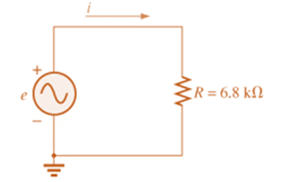
Fig. 14.77
Expert Solution & Answer
Want to see the full answer?
Check out a sample textbook solution
Students have asked these similar questions
a diode current is 0.6 ma when applied voltage is 400 mv and 20 ma when applied voltage is 500 mv.find n.assume vt=26mv
4. Impedance of each leg of the load is 2+j2 ohms. Find the 3-phase power consumed by the loads.
I need help with this problem and an explanation of the solution for the image described below. (Introduction to Signals and Systems)
Chapter 14 Solutions
Laboratory Manual for Introductory Circuit Analysis
Ch. 14 - Plot the following waveform versus time showing...Ch. 14 - Repeat Problem 1 for the following sinusoidal...Ch. 14 - What is the derivative of each of the following...Ch. 14 - The voltage across a 20 resistor is as indicated....Ch. 14 - The current through a 6.8 k ) resistor is as...Ch. 14 - Determine the inductive reactance (in ohms) of a 2...Ch. 14 - Determine the closest standard value inductance...Ch. 14 - Determine the frequency at which a 47 mH...Ch. 14 - The current through a 20 inductive reactance is...Ch. 14 - The current through a 0.1 H coil is given. What is...
Ch. 14 - The voltage across a 40 inductive reactance is...Ch. 14 - The voltage across a 0.2 H coil is given. What is...Ch. 14 - Determine the capacitive reactance (in ohms) of a...Ch. 14 - Determine the closest standard value capacitance...Ch. 14 - Determine the frequency at which a 3.9 F capacitor...Ch. 14 - The voltage across a 2.5 capacitive reactance is...Ch. 14 - The voltage across a 1 F capacitor is given. What...Ch. 14 - The current through a 2 k capacitive reactance is...Ch. 14 - The current through a 0.56 F capacitor is given....Ch. 14 - For the following pairs of voltages and currents,...Ch. 14 - Repeat Problem 20 for the following pairs of...Ch. 14 - Plot XL versus frequency for a 3 mH coil using a...Ch. 14 - Plot XC versus frequency for a 1 F capacitor using...Ch. 14 - At what frequency will the reactance of a 1 F...Ch. 14 - The reactance of a coil equals the resistance of a...Ch. 14 - Determine the frequency at which a 1 F capacitor...Ch. 14 - Determine the capacitance required to establish a...Ch. 14 - Find the average power loss and power factor for...Ch. 14 - If the current through and voltage across an...Ch. 14 - A circuit dissipates 100 W (average power) at 150...Ch. 14 - The power factor of a circuit is 0.5 lagging. The...Ch. 14 - In Fig.14.77, e=120sin(260t+20). a. What is the...Ch. 14 - In Fig. 14.78, e=220sin(1000t+60). a. Find the...Ch. 14 - In Fig. 14.79, i=30103sin(2500t20). a. Find the...Ch. 14 - For the network in Fig. 14.80 and the applied...Ch. 14 - For the network in Fig. 14.81 and the applied...Ch. 14 - Convert the following from rectangular to polar...Ch. 14 - Convert the following from rectangular to polar...Ch. 14 - Convert the following from polar to rectangular...Ch. 14 - Convert the following from polar to rectangular...Ch. 14 - Perform the following additions in rectangular...Ch. 14 - Perform the following subtractions in rectangular...Ch. 14 - Perform the following operations with polar...Ch. 14 - Perform the following multiplications in...Ch. 14 - Perform the following multiplications in polar...Ch. 14 - Perform the following divisions in polar form:...Ch. 14 - Perform the following divisions, and leave the...Ch. 14 - Perform the following operations, and express your...Ch. 14 - Prob. 49PCh. 14 - Determine a solution for x and y if...Ch. 14 - Determine a solution for x and y if...Ch. 14 - Express the following in phasor from:...Ch. 14 - Express the following in phasor form:...Ch. 14 - Express the following phasor currents and voltages...Ch. 14 - For the system in Fig. 14.82, find the sinusoidal...Ch. 14 - For the system in Fig. 14.83 find the sinusoidal...Ch. 14 - Find the sinusoidal expression for the voltage Ua...Ch. 14 - Find the sinusoidal expression for the current i1...Ch. 14 - Plot icandUc versus time for the network in Fig....Ch. 14 - Plot the magnitude and phase angle of the current...Ch. 14 - Plot the total impedance of the configuration in...
Knowledge Booster


Learn more about
Need a deep-dive on the concept behind this application? Look no further. Learn more about this topic, electrical-engineering and related others by exploring similar questions and additional content below.Similar questions
- Using C-H Theorem to find A2, A3 for A=( 6 6arrow_forward- Apply the Gauss-Jordan method to the following system: X1 X2 X3+ x4 = 1 X1+2x2+2x3 + 2x4 = 0 X1+2x2+3x3 + 3x4 = 0 X1+2x2+3x3 + 4x4 = 0arrow_forwardSolve the following circuit using Gauss Elimination method, V/R=1; R R R R 1 R 12 13 V Varrow_forward
- NEED HANDWRITTEN SOLUTION DO NOT USE AIarrow_forwardI need help with this problem and an explanation of the solution for the image described below. (Introduction to Signals and Systems)arrow_forwardI need help with this problem and an explanation of the solution for the image described below. (Introduction to Signals and Systems)arrow_forward
arrow_back_ios
SEE MORE QUESTIONS
arrow_forward_ios
Recommended textbooks for you
 Power System Analysis and Design (MindTap Course ...Electrical EngineeringISBN:9781305632134Author:J. Duncan Glover, Thomas Overbye, Mulukutla S. SarmaPublisher:Cengage Learning
Power System Analysis and Design (MindTap Course ...
Electrical Engineering
ISBN:9781305632134
Author:J. Duncan Glover, Thomas Overbye, Mulukutla S. Sarma
Publisher:Cengage Learning
Inductors Explained - The basics how inductors work working principle; Author: The Engineering Mindset;https://www.youtube.com/watch?v=KSylo01n5FY;License: Standard Youtube License