Concept explainers
(a)
Perform the mathematical operation of
(a)
Answer to Problem 25P
The mathematical operation
Explanation of Solution
Given data:
Calculation:
To find
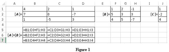
Refer to the Figure 1:
First type the appropriate characters and values in the Excel sheet. In the cell A6, type the operation as “
Likewise select by using left mouse button, pick cells from B5 through D7 and click in the formula bar, then holding down the ctrl and the Shift Key, press the Enter key. Thus, the result is obtained as shown in Figure 2.
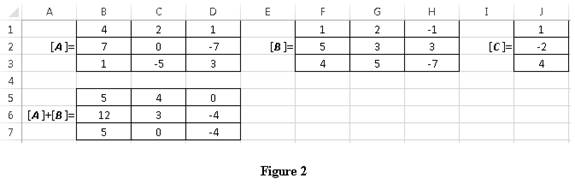
Conclusion:
Hence, the mathematical operation
(b)
Perform the mathematical operation of
(b)
Answer to Problem 25P
The mathematical operation
Explanation of Solution
Given data:
Calculation:
To find
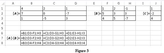
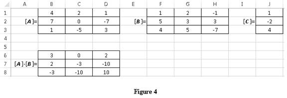
Refer to the Figure 3:
First type the appropriate characters and values in the Excel sheet. In the cell A7, type the operation as “
Likewise select by using left mouse button, pick cells from B6 through D8 and click in the formula bar, then holding down the ctrl and the Shift Key, press the Enter key. Thus, the result is obtained as shown in Figure 4.
Conclusion:
Hence, the mathematical operation
(c)
Perform the mathematical operation
(c)
Answer to Problem 25P
The mathematical operation
Explanation of Solution
Given data:
Calculation:
To find
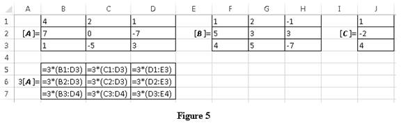
Refer to the Figure 5:
First type the appropriate characters and values in the Excel sheet. In the cell A6, type the operation as “
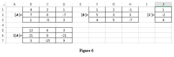
Likewise select by using left mouse button, pick cells from B5 through D7 and click in the formula bar, then holding down the ctrl and the Shift Key, press the Enter key. Thus, the result is obtained as shown in Figure 6.
Conclusion:
Hence, the mathematical operation
(d)
Perform the mathematical operation of
(d)
Answer to Problem 25P
The mathematical operation
Explanation of Solution
Given data:
Calculation:
To find
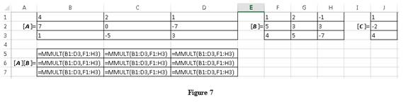
Refer to the Figure 7:
First type the appropriate characters and values in the Excel sheet. In the cell A6, type the operation as “
Likewise select by using left mouse button, pick cells from B5 through D7 and click in the formula bar, then holding down the ctrl and the Shift Key, press the Enter key. Thus, the result is obtained as shown in Figure 8.
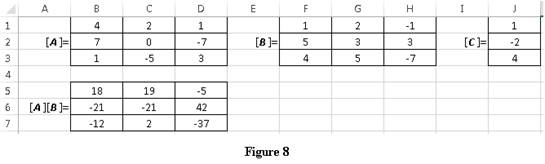
Conclusion:
Hence, the mathematical operation
(e)
Perform the mathematical operation of
(e)
Answer to Problem 25P
The mathematical operation
Explanation of Solution
Given data:
Calculation:
To find
Refer to the Figure 9:
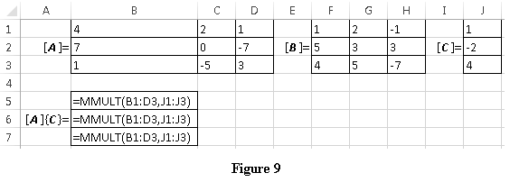
First type the appropriate characters and values in the Excel sheet. In the cell A6, type the operation as “
Likewise select by using left mouse button, pick cells from B5 through B7 and click in the formula bar, then holding down the ctrl and the Shift Key, press the Enter key. Thus, the result is obtained as shown in Figure 10.
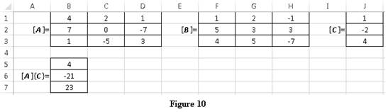
Conclusion:
Hence, the mathematical operation
Want to see more full solutions like this?
Chapter 14 Solutions
Engineering Fundamentals: An Introduction to Engineering


- 9.44 High-speed passenger trains are streamlined to reduce shear force. The cross section of a passenger car of one such train is shown. For a train 81 m long, estimate the shear force (a) for a speed of 81.1 km/hr and (b) for one of 204 km/hr. What power is required for just the shear force at these speeds? These two power calculations will be answers (c) and (d), respectively. Assume T = 10°C and that the boundary layer is tripped at the front of the train. 10 m Problem 9.44arrow_forwardA monitoring program for water flow in an unsaturated soil layer includes sensors to measure the volumetric water content and suction up to a depth of 3 m. The soil is a sand whose hydraulic properties are shown in the figures below. Using the drying curves, draw a quantitatively accurate set of vertical profiles of volumetric water content, pressure head, and total hydraulic head versus depth (with a datum at the base of the soil layer and an elevation head that is positive upward) expected for the following cases:A) The volumetric water content (moisture content) is 10% throughout the profile B) The pressure head is -150 cm throughout the profile C) The total hydraulic head is 100 cm throughout the profile (static no-flow case) Also, report the hydraulic gradient for each case. For parts (a) and (b), calculate the flow rates through the profile. For part (c), calculate the depth to the water table.arrow_forward9.16 Two vertical parallel plates are spaced 0.012 ft apart. If the pressure decreases at a rate of 100 psf/ft in the vertical z direction in the fluid between the plates, what is the maximum fluid velocity in the Z direction? The fluid has a viscosity of 10-3 Ibf s/ft² and a specific gravity of 0.80. .arrow_forward
- Please explain steps using software.arrow_forwardPlease explain steps for using softwarearrow_forwardDesign the reinforced masonry beam in the wall shown below. The wall is to be constructed of fully grouted hollow concrete masonry units in running bond. It is to carry its own weight plus a superimposed dead load of 2.5 kips/ft and a live load of 0.8 kip/ft. Determine the width of the masonry units (by trials), and the amounts of the longitudinal and shear reinforcement required using the strength design method of TMS 402-22. Show the layout of the reinforcements with diagrams. Use fm = 2,000 psi, Grade 60(60 ksi) steel, and Type S Portland cement mortar. Assume that the centroid of the bottom rebar is 3 inches from the bottom face of the beam. ( you may assume that the unit weight of fully grouted concrete masonry is 125 lbs per cubic foot.)arrow_forward
- 6. The easiest method to solve the beam shown in question number 14 is A. Force method B. Slope deflection method C. Moment distribution method D. Virtual work method E. Stiffness matrix method 17. The value of 8 caused by applying CW moment at A equal to 18. A. ML/2E1 B. ML/3E1 C. ML/4E1 D. ML/6EI E. None of the above For the beam shown below, the moment at A kN.m CCW. Assume P= 8 kN equals to ........ A. 20 B. 22.5 C. 25 D. 27.5 E. 30 M L A unlocked joint end pin P P P B A 1m 1m 2m 2m 19. The analysis of indeterminate non sway frames using moment distribution method does not need..... A. Finding stiffness factors of members B. Finding fix end moments C. Using compatibility equations D. Removing redundants E. Cand D 0. The frame shown is kinematically 6 kN/m indeterminate to ................ degree. A, C and D are fixed. E and B are pinned. A. First B. Second C. Third D. Fourth E. None of the above 6 m Sm 7 marrow_forward1. The moment at A using slope deflection method equals to 10 kN ..... kN. m CCW. A. 2.5 B. 5 C. 7.5 D. 10 E. None of the above 2m 2m B 10 kN + 2m + 2m 2. To solve the beam shown using slope deflection method,. ...... unknowns (s) 25 kN 15 kN/m should be selected. A. One B. Two fix C. Three D. Four E. None of the above magnitude of the rotation at B for the me shown using slope deflection method quals to El constant. A. -162/EI B. -162 El C. 40/El D. -40 El E. 0.3 radian B A 3 m 3 m -4 m- 4k/ft roller A fix 18 ft. To solve the beam shown using slope deflection method, should be fix selected as equilibrium equation (s). A. MAB+MBA = 0 B. MAB + MBA 0 and MBC=0 C. MBA+MBC = 0 D. MBA+MBC = 0 and MCB=0 E. None of the above B fix fix 9ft 20 kN/m 80 EN pin 9 m 3 m rollerarrow_forwardSolvearrow_forward
- 5. The number of unknowns for the frame shown using slope deflection method is... Assume A, B and D are fixed and interior hinge at C A. Two B. Four C. Six D. Eight E. None of the above 10 kN B Qc 4m A 3m + + 3m 3m 6. 7. The slope-deflection method was originally developed by Heinrich Manderla and Otto Mohr for the purpose of studying. A. secondary stresses in trusses B. secondary stresses in beams and frames C. Indeterminate beams and frames analysis D. Determinate beams and frames analysis E. None of the above In structures that have non-parallel end members, the displacement of the members will be..... A. Similar B. Different C. Proportional D. Zero E. None of the above. 8. The magnitude of the fix end moment at A 4k/ft using slope deflection method equals to pin exfix ...........k. ft. A. 25 B. -25 C. 40 D. -40 E. None of the above. A roller 15 ft- 12 f The magnitude of MBC for the frame shown in question number 3 using slope deflection method equals Assume El constant for all…arrow_forwardQ2. An isotropic rectangular slab (6 x 8) m is fixed at 3- edges and free at one edge as shown below. The reinforcement provides a positive yield moment of (10) kN.m/m and along the fixed edge a negative yield moment (m) of (14) kN.m/ m. Determine the collapse load if the slab carries a u.d.L. of (w) kN/m² including the slab own weight. W free C Gm fixed 8 m darrow_forwardReinforced Concrete Design 4 Second Monthly Exam 15/4/2025 Q1. A double T-concrete beam is prestressed with 2- tendons each of cross-sectional area of (600) mm² as shown below. Determine the allowable service load. Given: Span = 12 m, fse=1400 N/mm², fé= 50 N/mm², Ct = 163 mm, Cb =437 mm, I=7586 x 10 mm*. 10 KN/M * 25.00 x-500x 1500 +500 +100 163 不 -A 500 12m + 437 += 50 1 150 150 600mm 600mmarrow_forward
 Engineering Fundamentals: An Introduction to Engi...Civil EngineeringISBN:9781305084766Author:Saeed MoaveniPublisher:Cengage Learning
 Fundamentals Of Construction EstimatingCivil EngineeringISBN:9781337399395Author:Pratt, David J.Publisher:Cengage,