
Concept explainers
Using excel, plot the graph shows the deflection of a beam and also calculate the maximum deflection of the beam.
Answer to Problem 12P
Using excel, a table and graph is created to shows the deflection of a beam and the maximum deflection of the beam is
Explanation of Solution
Given data:
The length of the cantilever beam is
The modulus of elasticity
That is,
The second moment of area
That is,
The distributed load
Formula used:
Formula to calculate the deflection of the cantilever of the beam is,
Here,
Calculation:
Consider the distance (x) from the support as shown with the range from
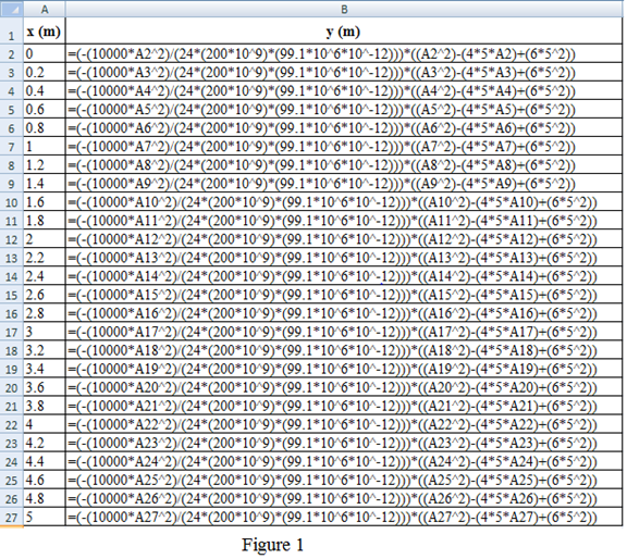
Refer to the Figure 1:
Column A shows the distance
Column B shows the deflection
Here, A2 cell represent the distance
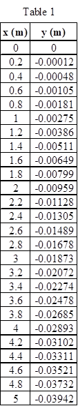
Table 1 shows the distance
Refer to the Figure 14.16 in the textbook.
Draw the graph for the distance
For X-axis, scale change is done by clicking the Layout on toolbar and picks the “Axes”. Choose the primary horizontal axis and select the “More Primary Horizontal Axis Options”. A dialog box of Format axis shows the axis option in that click the fixed and type the minimum value as 0, maximum value as 5, and major unit as 1 and minor unit as 0.2 and click the close option.
Likewise for Y-axis, scale change is done by clicking the Layout on toolbar and picks the “Axes”. Choose the primary vertical axis and select the “More Primary Vertical Axis Options”. A dialog box of Format axis shows the axis option in that click the fixed and type the minimum value as
Figure 2 shows the curve of the deflection of a cantilever beam.
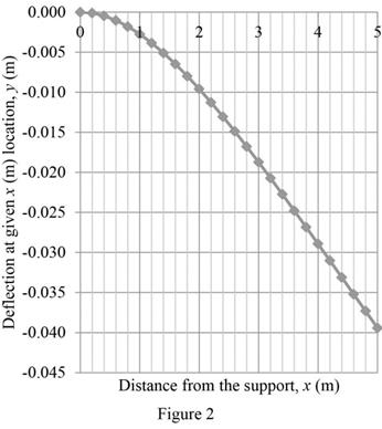
For the maximum deflection of the beam, the distance
That is,
Given,
Substitute the unit
Substitute
Thus, the maximum deflection of the beam is
Conclusion:
Hence, a table and graph is created using excel to shows the deflection of a beam and the maximum deflection of the beam is
Want to see more full solutions like this?
Chapter 14 Solutions
Engineering Fundamentals: An Introduction to Engineering


- Solve for forces on pin C and Darrow_forwardBorrow pit soil is being used to fill an 900,00 yd3 of depression. The properties of borrowpit and in-place fill soils obtained from laboratory test results are as follows:• Borrow pit soil: bulk density 105 pcf, moisture content = 8%, and specific gravity = 2.65• In-place fill soil: dry unit weight =120 pcf, and moisture content = 16%(a) How many yd3 of borrow soil is required?(b) What water mass is needed to achieve 16% moisture in the fill soil?(c) What is the in-place density after a long rain?arrow_forwardsolve for dt/dx=f(t,x)=x+t^2arrow_forward
- Calculate the BMs (bending moments) at all the joints of the beam shown in Fig.1 using the slope deflection method, draw the resulting shear force diagran and bending moment diagram. The beam is subjected to an UDL of w=65m. L=4.5m, L1= 1.8m. Assume the support at C is pinned, and A and B are roller supports. E = 200 GPa, I = 250x106 mm4.arrow_forwardProblem 2 (A is fixed and C is a pin) Find the reactions and A and C. 10 k- 6 ft 6 ft B A 2 k/ft 15 ftarrow_forward6. A lake with no outlet is fed by a river with a constant flow of 1200 ft3/s. Water evaporates from the surface at a constant rate of 13 ft3/s per square mile of surface area. The surface area varies with the depth h (in feet) as A (square miles) = 4.5 + 5.5h. What is the equilibrium depth of the lake? Below what river discharge (volume flow rate) will the lake dry up?arrow_forward
- Problem 5 (A, B, C and D are fixed). Find the reactions at A and D 8 k B 15 ft A -20 ft C 10 ft Darrow_forwardProblem 4 (A, B, E, D and F are all pin connected and C is fixed) Find the reactions at A, D and F 8 m B 6m E 12 kN D F 4 marrow_forwardProblem 1 (A, C and D are pins) Find the reactions and A, C and D. D 6 m B 12 kN/m 8 m A C 6 marrow_forward
- Uniform Grade of Pipe Station of Point A is 9+50.00. Elevation Point A = 250.75.Station of Point B is 13+75.00. Elevation Point B = 244.10 1) Calculate flowline of pipe elevations at every 50 ft. interval (Half Station). 2) Tabulate station and elevation for each station like shown on example 3) Draw Sketcharrow_forward40m 150N B 40marrow_forwardquantity surveyingarrow_forward
 Engineering Fundamentals: An Introduction to Engi...Civil EngineeringISBN:9781305084766Author:Saeed MoaveniPublisher:Cengage Learning
 Residential Construction Academy: House Wiring (M...Civil EngineeringISBN:9781285852225Author:Gregory W FletcherPublisher:Cengage Learning