Delmar's Standard Textbook Of Electricity
7th Edition
ISBN: 9781337900348
Author: Stephen L. Herman
Publisher: Cengage Learning
expand_more
expand_more
format_list_bulleted
Textbook Question
Chapter 14, Problem 1RQ
Which trigonometric function is used to find the angle if the length of the hypotenuse and of the adjacent side are known?
Expert Solution & Answer
To determine
The trigonometric function that is used to find the angle if the length of the hypotenuse and length of the adjacent side are known.
Answer to Problem 1RQ
Cosine functionis used to find the angle if the length of the hypotenuse and length of the adjacent side are known.
Explanation of Solution

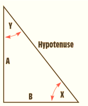
In the figure above,
A: Side opposite to angle X, adjacent to angle Y
B: Side opposite to angle Y, adjacent to angle X
Hence,
Hypotenuse, side A and angle Y are related as : cos Y = side A/Hypotenuse
Hypotenuse, side B and angle X are related as : cos X = side B/Hypotenuse
Want to see more full solutions like this?
Subscribe now to access step-by-step solutions to millions of textbook problems written by subject matter experts!
Students have asked these similar questions
Measure the impedance (magnitude and phase) of the inductor including the internal resistance at a frequency of1kHz. (Determine the reactance and internal resistance of the inductor.)
How would use of an osciloscope help solve this problem?
not use ai please
Sketch the phasor diagram of the peak voltage across the capacitor VC and peak current IC in the circuit shownbelow.
How would use of an osciloscope aid in solving this problem?
Chapter 14 Solutions
Delmar's Standard Textbook Of Electricity
Ch. 14 - 1. Which trigonometric function is used to find...Ch. 14 - 2. If side A has a length of 18.5 ft and side B...Ch. 14 - Prob. 3RQCh. 14 - Prob. 4RQCh. 14 - 5. The hypotenuse has a length of 65 in., and side...Ch. 14 - Prob. 6RQCh. 14 - Prob. 7RQCh. 14 - Prob. 8RQCh. 14 - Using the dimensions in Question 8, what is the...Ch. 14 - Prob. 10RQ
Knowledge Booster
Learn more about
Need a deep-dive on the concept behind this application? Look no further. Learn more about this topic, electrical-engineering and related others by exploring similar questions and additional content below.Similar questions
- Sketch the phasor diagram of the rms voltage across the inductor vL and rms source VS in the circuit shown below. how would use of an osciloscope help solve this problem?arrow_forwardThe attached waveform VS displayed on the oscilloscope approximate the following quantities.1. The peak voltage.2. The peak-to-peak voltage.3. The frequency of the waveform.4. The difference in time that corresponds to a 72 degree phase shift for this waveform. How would use of an osciloscope aid in solving this problem?arrow_forwardVs -J XcR Wo R²=3JRX < -Xc * Xc = ± Wc How do I make this Vs equation Look? ✓ = 3 + 1 (RWC- RWC) Vo 3+arrow_forward
- Draw the complete circular stator winding for a three phase delta connected AC generator consisting of 4 poles and 24 slots using a parallel connection. Your submission must consist of two drawings as follows: One drawing must show the winding arrangement of the phasegroups in the slots of the stator highlighting the start and finish of each phasegroup The other drawing must show only the end connections of each phase group for a parallel connection of the phasegroups and a delta connection of the phases The use of AutoCad or any other software is encouraged.arrow_forwardFor the oscillator resonance circuit shown in Fig. (5), derive the oscillation frequency, Feedback and open-loop gains. R1 C1 C2 ww R2 HH Fig.(5)arrow_forwardFor the oscillator resonance circuit shown in Fig. (5), derive the oscillation frequency, Feedback and open-loop gains. Vo L C I C ли ER Vsarrow_forward
- not use aiarrow_forwardFor the Fig. name, derive and determine all gains, frequency and draw the output waveform. Choose Q-15, and Q=6. Choose C₁-20 µF, C₂-5 µF, L=25mH. R₂ 12 HHarrow_forward1. (30pts) The input to a system is a DC component, a message, m(t), and a carrier, c(t). The output of the system is the square of the sum of the inputs. Determine if it is possible to retrieve DSB-SC modulated waveform. Show your work.arrow_forward
arrow_back_ios
SEE MORE QUESTIONS
arrow_forward_ios
Recommended textbooks for you
 Introductory Circuit Analysis (13th Edition)Electrical EngineeringISBN:9780133923605Author:Robert L. BoylestadPublisher:PEARSON
 Delmar's Standard Textbook Of ElectricityElectrical EngineeringISBN:9781337900348Author:Stephen L. HermanPublisher:Cengage Learning
 Programmable Logic ControllersElectrical EngineeringISBN:9780073373843Author:Frank D. PetruzellaPublisher:McGraw-Hill Education
 Fundamentals of Electric CircuitsElectrical EngineeringISBN:9780078028229Author:Charles K Alexander, Matthew SadikuPublisher:McGraw-Hill Education
 Electric Circuits. (11th Edition)Electrical EngineeringISBN:9780134746968Author:James W. Nilsson, Susan RiedelPublisher:PEARSON
 Engineering ElectromagneticsElectrical EngineeringISBN:9780078028151Author:Hayt, William H. (william Hart), Jr, BUCK, John A.Publisher:Mcgraw-hill Education,

Introductory Circuit Analysis (13th Edition)
Electrical Engineering
ISBN:9780133923605
Author:Robert L. Boylestad
Publisher:PEARSON

Delmar's Standard Textbook Of Electricity
Electrical Engineering
ISBN:9781337900348
Author:Stephen L. Herman
Publisher:Cengage Learning

Programmable Logic Controllers
Electrical Engineering
ISBN:9780073373843
Author:Frank D. Petruzella
Publisher:McGraw-Hill Education

Fundamentals of Electric Circuits
Electrical Engineering
ISBN:9780078028229
Author:Charles K Alexander, Matthew Sadiku
Publisher:McGraw-Hill Education

Electric Circuits. (11th Edition)
Electrical Engineering
ISBN:9780134746968
Author:James W. Nilsson, Susan Riedel
Publisher:PEARSON

Engineering Electromagnetics
Electrical Engineering
ISBN:9780078028151
Author:Hayt, William H. (william Hart), Jr, BUCK, John A.
Publisher:Mcgraw-hill Education,
The Divergence Theorem; Author: Professor Dave Explains;https://www.youtube.com/watch?v=vZGvgru4TwE;License: Standard Youtube License