
Concept explainers
Videos
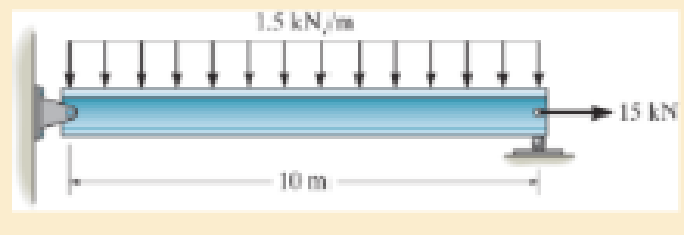
A = 2300 mm2, I = 9.5(106) mm4.
R14–1
Answer to Problem 14.146RP
The total axial and bending strain energy in the A992 steel beam is
Explanation of Solution
Given information:
The cross-sectional area of the beam is
Moment of inertia of the beam is
Assumption:
The modulus of elasticity or Young’s modulus of theA992 steelis
Explanation:
Determine the reactions:
Entire beam:
Show the free body diagram of the entire beam as in Figure 1.
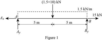
Moment about the point A:
Determine the vertical reaction at point B by taking moment about point A.
Along the vertical direction:
Determine the vertical reaction at point B by resolving the vertical component of forces.
Along the horizontal direction:
Determine the horizontal reaction at point A by resolving the horizontal component of force.
Show the calculation of reaction as follows:
Solve Equation (1).
Substitute 7.5kN for
Solve Equation (3).
Region
Show the free-body diagram of the section as in Figure 2.
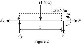
Moment about the section:
Determine the moment at section by taking moment about the section.
Along the horizontal direction:
Determine the normal axial force at the section by resolving the horizontal component of forces.
Show the calculation of values as follows:
Substitute 7.5kN for
Substitute 15 kN for
Strain energy due to axial load:
Determine the strain energy of a bar of constant cross-sectional area A and constant internal axial load N using the equation.
Here, N is the axial load, L is the length of beam, E is Young’s modulus or modulus of elasticity, and A is cross-sectional area of the beam.
Substitute 15 kN for N, 10 m for L,
Strain energy due to Bending:
Determine the strain energy in the beam due to bending using the equation.
Here, M is the moment in the beam and I is the moment of inertia of the beam.
Substitute 10 m for L,
Total strain energy:
Determine the total strain energy by adding the strain energy due to axial load and the strain energy due to bending.
Substitute 2.4456 J for
Thus, the total axial and bending strain energy in the A992 steel beam is
Want to see more full solutions like this?
Chapter 14 Solutions
MECHANICS OF MATERIALS-TEXT
Additional Engineering Textbook Solutions
Management Information Systems: Managing The Digital Firm (16th Edition)
Database Concepts (8th Edition)
BASIC BIOMECHANICS
Java: An Introduction to Problem Solving and Programming (8th Edition)
Elementary Surveying: An Introduction To Geomatics (15th Edition)
Electric Circuits. (11th Edition)


- Calculate the Shear Force at Point F on the beam below. Keep your answer in Newtons and make shear force positive to the right. A х 2m <2m E D 5m 1m Хт 325N1m 400N/m 8arrow_forwardThe normal force at C on the beam below is equal to: A ShN C X 15h N 8 ○ OkN 2.5kN 10kN ○ 12.5kN 1m Im 1m 1m;arrow_forwardCalculate the y coordinate of the of the centroid of the shape below. Take A= 18.5 8 6A 4A X 6Aarrow_forward
- In MATLAB write out a program to integrate the equations of motion of a rigid body. The inertia matrix is given by I = [125 0 0; 0 100 0; 0 0 75] which is a diagonal, where diag operator provides a matrix with given elements placed on its diagonal. Consider three cases where the body rotates 1 rad/sec about each principal axis. Integrate the resulting motion and study the angular rates and the resulting attitude (use any attitude coordinates). For each principal axis case, assume first that a pure spin about the principal axis is performed, and then repeat the simulation where a small 0.1 rad/sec motion is present about another principal axis. Discuss the stability of each motion. The code should produce a total of 6 simulations results when it is ran.arrow_forwardQ. A strain gauge rosette that is attached to the surface of a stressed component C). If the strain gauge rosette is of the D° gives 3 readings (a = A, b = B, &c = type (indicating the angle between each of the gauges), construct a Mohr's Strain Circle overleaf. You should assume that gauge A is aligned along the x-axis. Using the Mohr's Strain Circle calculate the: [10 marks] 100 918 ucy evods gringiz ya mwo quoy al etsede 39 926919 (i) principal strains (1, 2)? (au) oniona [5 marks] (ii) principal angles (1, 2)? You should measure these anticlockwise from the y-axis. 20 [5 marks] (iii) maximum shear strain in the plane (ymax)? Ex = Ea Ey = εc [5 marks] (epol) (apob) é Ea = A = -210 2 B=E₁ = -50 E₁ = C = 340 D = 45° bril elled ✓A bedivordan nemigas olloho shot on no eonsoup Imeneo alubom shine sail-no viss ieqse sidetiva bnat sabied 2arrow_forward1) Solve and show which is converage or diyverage a = 2+(0.1)" 3 16) a = n 1-2n 2) a = In n 1+2n 17) a = n 1-5n4 3) an = n* +8n³ 18) a =√4"n n² -2n+1 n! 20) a = 4) a₁ = 10 n-1 (Ina) 5) a=1+(-1)" 21) a= 6) a 7) an = * = (12+) (1-1) 2n (-1)+1 2n-1 3n+1 22) a= 3n-1 x" 23) a= .x>0 2n+1 2n 3"x6" 8) a = 24) a = n+1 π 9) a = sin 2 sin n 10) an = n + 2 x n! 25) a = tanh(n) n² 1 26) a = -sin- 2n-1 27) a = tan(n) n n 11) a = 2" 12) a = n 13) a = 8/ +=(1+2)" 14) a = 15) a = √10n In(n+1) 29) a = n 30) an-√n²-1 1 28) a = + √2" (In n)200 n 31) a=- = 1 dx nixarrow_forward
- HW12 A multiple-disc clutch has five plates having four pairs of active friction surfaces. If the intensity of pressure is not to exceed 0.127 N/mm², find the power transmitted at 500 r.p.m. The outer and inner radii of friction surfaces are 125 mm and 75 mm respectively. Assume uniform wear and take the coefficient of friction = 0.3.arrow_forwardThe sketch below gives some details of the human heart at rest. What is the total power requirement (work/time) for an artificial heart pump if we use a safety factor of 5 to allow for inefficiencies, the need to operate the heart under stress, etc.? Assume blood has the properties of water. p pressure above atmosphere blood going to the lungs for a fresh charge of oxygen p = 2.9 kPa 25v pulmonary artery d = 25mm fresh oxygenated blood from the lungs p = 1.0 kPa vena cava d=30mm right auricle pulmonary vein, d = 28mm aorta, d=20mm spent blood returning from left auricle the body p = 0.66 kPa right left ventricle ventricle blood to feed the body, p 13 kPa normal blood flow = 90 ml/sarrow_forward4- A horizontal Venturi meter is used to measure the flow rate of water through the piping system of 20 cm I.D, where the diameter of throat in the meter is d₂ = 10 cm. The pressure at inlet is 17.658 N/cm2 gauge and the vacuum pressure of 35 cm Hg at throat. Find the discharge of water. Take Cd = 0.98.arrow_forward
 Elements Of ElectromagneticsMechanical EngineeringISBN:9780190698614Author:Sadiku, Matthew N. O.Publisher:Oxford University Press
 Mechanics of Materials (10th Edition)Mechanical EngineeringISBN:9780134319650Author:Russell C. HibbelerPublisher:PEARSON
 Thermodynamics: An Engineering ApproachMechanical EngineeringISBN:9781259822674Author:Yunus A. Cengel Dr., Michael A. BolesPublisher:McGraw-Hill Education
 Control Systems EngineeringMechanical EngineeringISBN:9781118170519Author:Norman S. NisePublisher:WILEY
 Mechanics of Materials (MindTap Course List)Mechanical EngineeringISBN:9781337093347Author:Barry J. Goodno, James M. GerePublisher:Cengage Learning
 Engineering Mechanics: StaticsMechanical EngineeringISBN:9781118807330Author:James L. Meriam, L. G. Kraige, J. N. BoltonPublisher:WILEY