
Concept explainers
Using excel, plot the graph shows the deflection of a beam and also calculate the maximum deflection of the beam.
Answer to Problem 12P
Using excel, a table and graph is created to shows the deflection of a beam and the maximum deflection of the beam is
Explanation of Solution
Given data:
The length of the cantilever beam is
The modulus of elasticity
That is,
The second moment of area
That is,
The distributed load
Formula used:
Formula to calculate the deflection of the cantilever of the beam is,
Here,
Calculation:
Consider the distance (x) from the support as shown with the range from
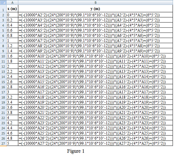
Refer to the Figure 1:
Column A shows the distance
Column B shows the deflection
Here, A2 cell represent the distance
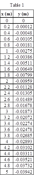
Table 1 shows the distance
Refer to the Figure 14.16 in the textbook.
Draw the graph for the distance
For X-axis, scale change is done by clicking the Layout on toolbar and picks the “Axes”. Choose the primary horizontal axis and select the “More Primary Horizontal Axis Options”. A dialog box of Format axis shows the axis option in that click the fixed and type the minimum value as 0, maximum value as 5, and major unit as 1 and minor unit as 0.2 and click the close option.
Likewise for Y-axis, scale change is done by clicking the Layout on toolbar and picks the “Axes”. Choose the primary vertical axis and select the “More Primary Vertical Axis Options”. A dialog box of Format axis shows the axis option in that click the fixed and type the minimum value as
Figure 2 shows the curve of the deflection of a cantilever beam.
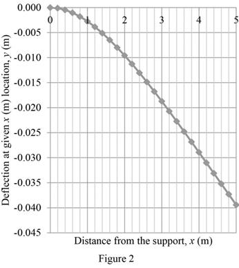
For the maximum deflection of the beam, the distance
That is,
Given,
Substitute the unit
Substitute
Thus, the maximum deflection of the beam is
Conclusion:
Hence, a table and graph is created using excel to shows the deflection of a beam and the maximum deflection of the beam is
Want to see more full solutions like this?
Chapter 14 Solutions
Engineering Fundamentals


- I need detailed help solving this exercise from homework of Engineering Mathematics II.I do not really understand how to do, please do it step by step, not that long but clear. Thank you!P.S.: Please do not use AI, thanks!arrow_forwardI need detailed help solving this exercise from homework of Engineering Mathematics II.I do not really understand how to do, please do it step by step, not that long but clear. Thank you!P.S.: Please do not use AI, thanks!arrow_forwardI need detailed help solving this exercise from homework of Engineering Mathematics II.I do not really understand how to do, please do it step by step, not that long but clear. Thank you!P.S.: Please do not use AI, thanks!arrow_forward
- I need detailed help solving this exercise from homework of Engineering Mathematics II.I do not really understand how to do, please do it step by step, not that long but clear. Thank you!P.S.: Please do not use AI, thanks!arrow_forwardI need detailed help solving this exercise from homework of Engineering Mathematics II.I do not really understand how to do, please do it step by step, not that long but clear. Thank you!P.S.: Please do not use AI, thanks!arrow_forwardI need detailed help solving this exercise from homework of Engineering Mathematics II.I do not really understand how to do, please do it step by step, not that long but clear. Thank you!P.S.: Please do not use AI, thanks!arrow_forward
- I need detailed help solving this exercise from homework of Engineering Mathematics II.I do not really understand how to do, please do it step by step, not that long but clear. Thank you!P.S.: Please do not use AI, thanks!arrow_forwardI need detailed help solving this exercise from homework of Engineering Mathematics II.I do not really understand how to do, please do it step by step, not that long but clear. Thank you!P.S.: Please do not use AI, thanks!arrow_forwardI need detailed help solving this exercise from homework of Engineering Mathematics II.I do not really understand how to do, please do it step by step, not that long but clear. Thank you!P.S.: Please do not use AI, thanks!arrow_forward
- I need detailed help solving this exercise from homework of Engineering Mathematics II.I do not really understand how to do, please do it step by step, not that long but clear. Thank you!P.S.: Please do not use AI, thanks!arrow_forwardI need detailed help solving this exercise from homework of Engineering Mathematics II.I do not really understand how to do, please do it step by step, not that long but clear. Thank you!P.S.: Please do not use AI, thanks!arrow_forwardI need detailed help solving this exercise from homework of Engineering Mathematics II.I do not really understand how to do, please do it step by step, not that long but clear. Thank you!P.S.: Please do not use AI, thanks!arrow_forward
 Engineering Fundamentals: An Introduction to Engi...Civil EngineeringISBN:9781305084766Author:Saeed MoaveniPublisher:Cengage Learning
 Residential Construction Academy: House Wiring (M...Civil EngineeringISBN:9781285852225Author:Gregory W FletcherPublisher:Cengage Learning