
Mechanics of Materials
10th Edition
ISBN: 9780134321158
Author: HIBBELER
Publisher: PEARSON
expand_more
expand_more
format_list_bulleted
Concept explainers
Videos
Textbook Question
Chapter 13.3, Problem 13.33P
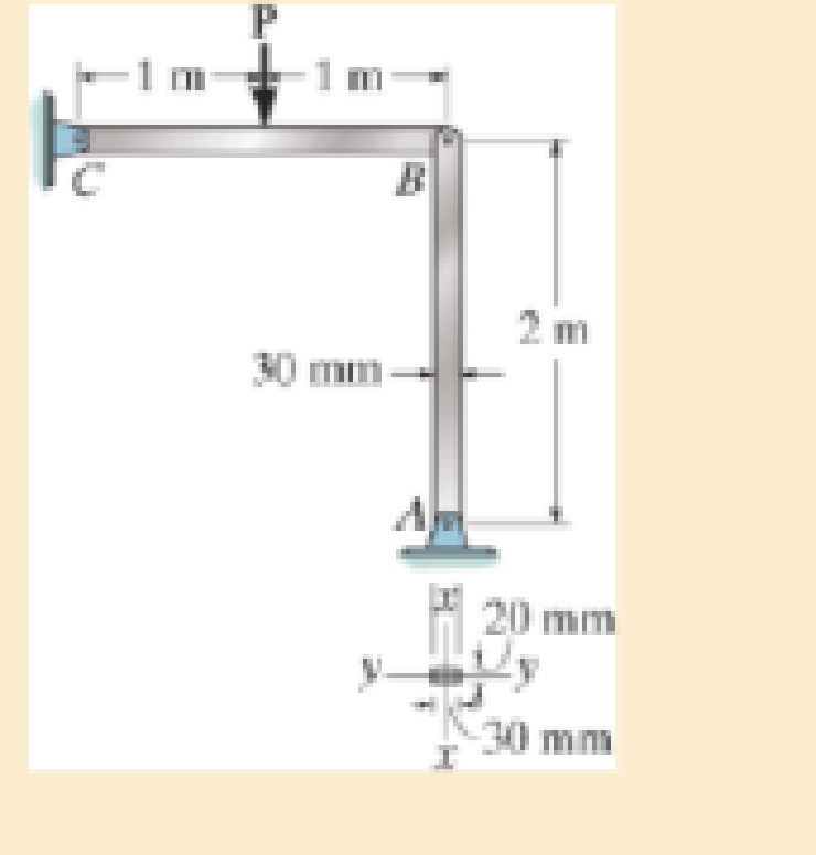
Determine the maximum allowable load P that can be applied to member BC without causing member AB to buckle. Assume that AB is made of steel and is pinned at its ends for x-x axis buckling and fixed at its ends for y-y axis buckling. Use a factor of safety with respect to buckling of F.S. = 3. Est = 200 GPa, σY = 360 MPa.
Expert Solution & Answer
Want to see the full answer?
Check out a sample textbook solution
Students have asked these similar questions
The gears shown in the figure have a diametral pitch of 2 teeth per inch and a 20° pressure angle.
The pinion rotates at 1800 rev/min clockwise and transmits 200 hp through the idler pair to gear
5 on shaft c. What forces do gears 3 and 4 transmit to the idler shaft?
TS
I
y
18T
32T
This
a
12
x
18T
C
48T
5
Question 1. Draw 3 teeth for the following pinion and gear respectively. The teeth
should be drawn near the pressure line so that the teeth from the pinion should
mesh those of the gear. Drawing scale (1:1). Either a precise hand drawing or
CAD drawing is acceptable. Draw all the trajectories of the involute lines and the
circles.
Specification: 18tooth pinion and 30tooth gear. Diameter pitch=P=6 teeth /inch.
Pressure angle:20°, 1/P for addendum (a) and 1.25/P for dedendum (b). For fillet,
c=b-a.
5. The figure shows a gear train. There is no friction at the bearings except for the gear tooth forces.
The material of the milled gears is steel having a Brinell hardness of 170. The input shaft speed (n2)
is 800 rpm. The face width and the contact angle for all gears are 1 in and 20° respectively. In this
gear set, the endurance limit (Se) is 15 kpsi and nd (design factor) is 2.
(a) Find the revolution speed of gear 5.
(b) Determine whether each gear satisfies the design factor of 2.0 for bending fatigue.
(c) Determine whether each gear satisfies the design factor of 2.0 for surface fatigue (contact stress).
(d) According to the computation results of the questions (b) and (c), explain the possible failure
mechanisms for each gear.
N4=28
800rpm
N₁=43
N5=34
N₂=14
P(diameteral pitch)=8 for all gears
Coupled to 2.5hp motor
Chapter 13 Solutions
Mechanics of Materials
Ch. 13.3 - A 50-in long steel rod has a diameter of 1 in....Ch. 13.3 - A 12-ft wooden rectangular column has the...Ch. 13.3 - The A992 steel column can be considered pinned at...Ch. 13.3 - A steel pipe is fixed supported at its ends. If it...Ch. 13.3 - Determine the maximum force P that can be...Ch. 13.3 - The A992 steel rod BC has a diameter of 50 mm and...Ch. 13.3 - Determine the critical buckling load for the...Ch. 13.3 - The column consists of a rigid member that is...Ch. 13.3 - The aircraft link is made from an A992 steel rod....Ch. 13.3 - Rigid bars AB and BC are pin connected at B. If...
Ch. 13.3 - A 2014-T6 aluminium alloy column has a length of 6...Ch. 13.3 - Solve Prob. 13-5 if the column is pinned at its...Ch. 13.3 - The W12 50 is made of A992 steel and is used as a...Ch. 13.3 - The W12 50 is made of A992 steel and is used as a...Ch. 13.3 - A steel column has a length of 9 m and is fixed at...Ch. 13.3 - A steel column has a length of 9 m and is pinned...Ch. 13.3 - The A992 steel angle has a cross-sectional area of...Ch. 13.3 - The 50-mm-diameter C86100 bronze rod is fixed...Ch. 13.3 - Determine the maximum load P the frame can support...Ch. 13.3 - The W8 67 wide-flange A-36 steel column can be...Ch. 13.3 - Prob. 13.15PCh. 13.3 - Prob. 13.16PCh. 13.3 - The 10-ft wooden rectangular column has the...Ch. 13.3 - The 10-fl wooden column has the dimensions shown....Ch. 13.3 - Determine the maximum force P that can be applied...Ch. 13.3 - The A-36 steel pipe has an outer diameter of 2 in....Ch. 13.3 - The A-36 steel pipe has an outer diameter of 2 in....Ch. 13.3 - The deck is supported by the two 40-mm-square...Ch. 13.3 - The deck is supported by the two 40-mm-square...Ch. 13.3 - The beam is supported by the three pin-connected...Ch. 13.3 - The W14 30 A992 steel column is assumed pinned at...Ch. 13.3 - The A992 steel bar AB has a square cross section....Ch. 13.3 - The linkage is made using two A992 steel rods,...Ch. 13.3 - The linkage is made using two A992 steel rods,...Ch. 13.3 - The linkage is made using two A-36 steel rods,...Ch. 13.3 - The linkage is made using two A-36 steel rods,...Ch. 13.3 - The steel bar AB has a rectangular cross section....Ch. 13.3 - Determine if the frame can support a load of P =...Ch. 13.3 - Determine the maximum allowable load P that can be...Ch. 13.3 - Prob. 13.34PCh. 13.3 - Prob. 13.35PCh. 13.3 - The members of the truss are assumed to be pin...Ch. 13.3 - Solve Prob. 1336 for member AB, which has a radius...Ch. 13.3 - The truss is made from A992 steel bars, each of...Ch. 13.3 - The truss is made from A992 steel bars, each of...Ch. 13.3 - Prob. 13.40PCh. 13.3 - The ideal column has a weight w (force/length) and...Ch. 13.3 - The ideal column is subjected to the force F at...Ch. 13.3 - The column with constant El has the end...Ch. 13.3 - Consider an ideal column as in Fig.13-10 c, having...Ch. 13.3 - Consider an ideal column as in Fig. 13-10d, having...Ch. 13.5 - The wood column is fixed at its base and free at...Ch. 13.5 - The W10 12 structural A-36 steel column is used...Ch. 13.5 - The W10 12 structural A-36 steel column is used...Ch. 13.5 - The aluminium column is fixed at the bottom and...Ch. 13.5 - Prob. 13.50PCh. 13.5 - Prob. 13.51PCh. 13.5 - The aluminum rod is fixed at its base and free and...Ch. 13.5 - Assume that the wood column is pin connected at...Ch. 13.5 - Prob. 13.54PCh. 13.5 - The wood column is pinned at its base and top. If...Ch. 13.5 - Prob. 13.56PCh. 13.5 - Prob. 13.57PCh. 13.5 - Prob. 13.58PCh. 13.5 - Prob. 13.59PCh. 13.5 - The wood column is pinned at its base and top. If...Ch. 13.5 - The brass rod is fixed at one end and free at the...Ch. 13.5 - The brass rod is fixed at one end and free at the...Ch. 13.5 - Prob. 13.63PCh. 13.5 - A W14 30 structural A-36 steel column is pin...Ch. 13.5 - Prob. 13.65PCh. 13.5 - The 6061-T6 aluminum alloy solid shaft is fixed at...Ch. 13.5 - The 6061-T6 aluminum alloy solid shaft is fixed at...Ch. 13.5 - The W14 53 structural A992 steel column is fixed...Ch. 13.5 - The W14 53 column is fixed at its base and free...Ch. 13.5 - Prob. 13.70PCh. 13.5 - The stress-strain diagram for a material can be...Ch. 13.5 - The stress-strain diagram for a material can be...Ch. 13.5 - The stress-strain diagram for the material of a...Ch. 13.5 - Construct the buckling curve, P/A versus L/ r, for...Ch. 13.5 - The stress-strain diagram of the material can be...Ch. 13.5 - The stress-strain diagram of the material can be...Ch. 13.5 - Prob. 13.77PCh. 13.6 - Determine the largest length of a W10 12...Ch. 13.6 - Using the AISC equations, select from AppendixB...Ch. 13.6 - Take Y = 50 ksi.Ch. 13.6 - Determine the longest length of a W8 31...Ch. 13.6 - Using the AISC equations, select from AppendixB...Ch. 13.6 - Prob. 13.83PCh. 13.6 - Using the AISC equations, select from AppendixB...Ch. 13.6 - Prob. 13.85PCh. 13.6 - Prob. 13.86PCh. 13.6 - Prob. 13.87PCh. 13.6 - Prob. 13.88PCh. 13.6 - Using the AISC equations, check if a column having...Ch. 13.6 - The beam and column arrangement is used in a...Ch. 13.6 - Prob. 13.91PCh. 13.6 - Prob. 13.92PCh. 13.6 - The 1-in.-diameter rod is used to support an axial...Ch. 13.6 - The 1-in.-diameter rod is used to support an axial...Ch. 13.6 - Prob. 13.95PCh. 13.6 - Prob. 13.96PCh. 13.6 - Prob. 13.97PCh. 13.6 - Prob. 13.98PCh. 13.6 - The tube is 0.25 in. thick, is made of 2014-T6...Ch. 13.6 - Prob. 13.100PCh. 13.6 - A rectangular wooden column has the cross section...Ch. 13.6 - Prob. 13.102PCh. 13.6 - Prob. 13.103PCh. 13.6 - The bar is made of aluminum alloy 2014-T6....Ch. 13.6 - Prob. 13.105PCh. 13.6 - Prob. 13.106PCh. 13.7 - The W8 15 wide-flange A-36 steel column is...Ch. 13.7 - Solve Prob.13-107 if the column is fixed at its...Ch. 13.7 - Prob. 13.109PCh. 13.7 - Prob. 13.110PCh. 13.7 - The W8 15 wide-flange A992 steel column is fixed...Ch. 13.7 - The W8 15 wide-flange A992 steel column is fixed...Ch. 13.7 - The W12 22 wide-flange A-36 steel column is fixed...Ch. 13.7 - Prob. 13.114PCh. 13.7 - Prob. 13.115PCh. 13.7 - Prob. 13.116PCh. 13.7 - A 20-ft-long column is made of aluminum alloy...Ch. 13.7 - A 20-ft-long column is made of aluminum alloy...Ch. 13.7 - The 2014-T6 aluminum hollow column is fixed at its...Ch. 13.7 - The 2014-T6 aluminum hollow column is fixed at its...Ch. 13.7 - Prob. 13.121PCh. 13.7 - Prob. 13.122PCh. 13.7 - Prob. 13.123PCh. 13.7 - Prob. 13.124PCh. 13.7 - The 10-in.-diameter utility pole supports the...Ch. 13.7 - Using the NFPA equations of Sec 13.6. and Eq....Ch. 13.7 - Prob. 13.127PCh. 13 - The wood column has a thickness of 4 in. and a...Ch. 13 - The wood column has a thickness of 4 in. and a...Ch. 13 - A steel column has a length of 5 m and is free at...Ch. 13 - The square structural A992 steel tubing has outer...Ch. 13 - If the A-36 steel solid circular rod BD has a...Ch. 13 - If P = 15 kip, determine the required minimum...Ch. 13 - The steel pipe is fixed supported at its ends. If...Ch. 13 - The W200 46 wide-flange A992-steel column can be...Ch. 13 - The wide-flange A992 steel column has the cross...Ch. 13 - The wide-flange A992 steel column has the cross...
Knowledge Booster


Learn more about
Need a deep-dive on the concept behind this application? Look no further. Learn more about this topic, mechanical-engineering and related others by exploring similar questions and additional content below.Similar questions
- 1. The rotating steel shaft is simply supported by bearings at points of B and C, and is driven by a spur gear at D, which has a 6-in pitch diameter. The force F from the drive gear acts at a pressure angle of 20°. The shaft transmits a torque to point A of TA =3000 lbĘ in. The shaft is machined from steel with Sy=60kpsi and Sut=80 kpsi. (1) Draw a shear force diagram and a bending moment diagram by F. According to your analysis, where is the point of interest to evaluate the safety factor among A, B, C, and D? Describe the reason. (Hint: To find F, the torque Tд is generated by the tangential force of F (i.e. Ftangential-Fcos20°) When n=2.5, K=1.8, and K₁ =1.3, determine the diameter of the shaft based on (2) static analysis using DE theory (note that fatigue stress concentration factors need to be used for this question because the loading condition is fatigue) and (3) a fatigue analysis using modified Goodman. Note) A standard diameter is not required for the questions. 10 in Darrow_forward3 N2=28 P(diametral pitch)=8 for all gears Coupled to 25 hp motor N3=34 Full depth spur gears with pressure angle=20° N₂=2000 rpm (1) Compute the circular pitch, the center-to-center distance, and base circle radii. (2) Draw the free body diagram of gear 3 and show all the forces and the torque. (3) In mounting gears, the center-to-center distance was reduced by 0.1 inch. Calculate the new values of center-to-center distance, pressure angle, base circle radii, and pitch circle diameters. (4)What is the new tangential and radial forces for gear 3? (5) Under the new center to center distance, is the contact ratio (mc) increasing or decreasing?arrow_forward2. A flat belt drive consists of two 4-ft diameter cast-iron pulleys spaced 16 ft apart. A power of 60 hp is transmitted by a pulley whose speed is 380 rev/min. Use a service factor (Ks) pf 1.1 and a design factor 1.0. The width of the polyamide A-3 belt is 6 in. Use CD=1. Answer the following questions. (1) What is the total length of the belt according to the given geometry? (2) Find the centrifugal force (Fc) applied to the belt. (3) What is the transmitted torque through the pulley system given 60hp? (4) Using the allowable tension, find the force (F₁) on the tight side. What is the tension at the loose side (F2) and the initial tension (F.)? (5) Using the forces, estimate the developed friction coefficient (f) (6) Based on the forces and the given rotational speed, rate the pulley set. In other words, what is the horse power that can be transmitted by the pulley system? (7) To reduce the applied tension on the tight side, the friction coefficient is increased to 0.75. Find out the…arrow_forward
- The tooth numbers for the gear train illustrated are N₂ = 24, N3 = 18, №4 = 30, №6 = 36, and N₁ = 54. Gear 7 is fixed. If shaft b is turned through 5 revolutions, how many turns will shaft a make? a 5 [6] barrow_forwardCE-112 please solve this problem step by step and give me the correct answerarrow_forwardCE-112 please solve this problem step by step and give me the correct answerarrow_forward
- CE-112 solve this problem step by step and give me the correct answer pleasearrow_forwardPlease do not use any AI tools to solve this question. I need a fully manual, step-by-step solution with clear explanations, as if it were done by a human tutor. No AI-generated responses, please.arrow_forwardPlease do not use any AI tools to solve this question. I need a fully manual, step-by-step solution with clear explanations, as if it were done by a human tutor. No AI-generated responses, please.arrow_forward
arrow_back_ios
SEE MORE QUESTIONS
arrow_forward_ios
Recommended textbooks for you
 Mechanics of Materials (MindTap Course List)Mechanical EngineeringISBN:9781337093347Author:Barry J. Goodno, James M. GerePublisher:Cengage Learning
 International Edition---engineering Mechanics: St...Mechanical EngineeringISBN:9781305501607Author:Andrew Pytel And Jaan KiusalaasPublisher:CENGAGE L
Mechanics of Materials (MindTap Course List)
Mechanical Engineering
ISBN:9781337093347
Author:Barry J. Goodno, James M. Gere
Publisher:Cengage Learning
International Edition---engineering Mechanics: St...
Mechanical Engineering
ISBN:9781305501607
Author:Andrew Pytel And Jaan Kiusalaas
Publisher:CENGAGE L
Column buckling; Author: Amber Book;https://www.youtube.com/watch?v=AvvaCi_Nn94;License: Standard Youtube License