
Videos
(a)
Find the impulsive force
(a)
Answer to Problem 13.148P
The impulsive force
Explanation of Solution
Given information:
The weight of the hammer (W) is
The velocity of the hammer
The acceleration due to gravity (g) is
Calculation:
Show the free body momentum diagram of the hammer head and anvil as Figure (1).
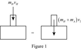
Use the principle of conservation of momentum to the impact of hammer head and anvil, to obtain the final velocity of anvil and hammer after the impact.
The expression for the principle of conservation of momentum as follows;
Initially the anvil is at rest, so the velocity will be zero.
Substitute 0 for
Show the free body impulse-momentum diagram of the hammer head as in Figure (2).
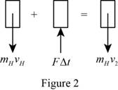
Use the principle of the impulse momentum to the hammer head to find the impulse exerted
The expression for the principle of the impulse momentum as follows;
Calculate the mass of the hammer
Substitute
The expression for the kinetic energy of the hammer before impact
Substitute
Calculate the final kinetic energy of the hammer and anvil system after the impact
Substitute
Substitute
Calculate the mass of the anvil
Here,
Substitute
Consider the equation (1).
Substitute
Consider the equation (2).
Substitute
Calculate the energy absorbed by the rivet
Consider the equation (3).
Substitute
Calculate the energy absorbed by the rivet under each blow
Substitute
Therefore, the impulsive force
(b)
Find the impulsive force
(b)
Answer to Problem 13.148P
The impulsive force
Explanation of Solution
Given information:
The weight of the hammer (W) is
The velocity of the hammer
The acceleration due to gravity (g) is
Calculation:
Calculate the impulse exerted by the rivet
Calculate the mass of the anvil
Substitute
Consider the equation (1).
Substitute
Consider the equation (2).
Substitute
Consider the equation (3).
Substitute
Calculate the energy absorbed by the rivet under each blow
Substitute
Want to see more full solutions like this?
Chapter 13 Solutions
Connect 1 Semester Access Card for Vector Mechanics for Engineers: Statics and Dynamics


- My ID#016948724 please solve this problems and show me every step clear to follow pleasearrow_forwardMy ID# 016948724arrow_forwardPlease do not use any AI tools to solve this question. I need a fully manual, step-by-step solution with clear explanations, as if it were done by a human tutor. No AI-generated responses, please.arrow_forward
- Please do not use any AI tools to solve this question. I need a fully manual, step-by-step solution with clear explanations, as if it were done by a human tutor. No AI-generated responses, please.arrow_forwardPlease do not use any AI tools to solve this question. I need a fully manual, step-by-step solution with clear explanations, as if it were done by a human tutor. No AI-generated responses, please.arrow_forward[Q2]: The cost information supplied by the cost accountant is as follows:Sales 20,00 units, $ 10 per unitCalculate the (a/ newsale guantity and (b) new selling price to earn the sameVariable cost $ 6 per unit, Fixed Cost $ 30,000, Profit $ 50,000profit ifi) Variable cost increases by $ 2 per unitil) Fixed cost increase by $ 10,000Ili) Variable cost increase by $ 1 per unit and fixed cost reduces by $ 10,000arrow_forward
- can you please help me perform Visual Inspection and Fractography of the attatched image: Preliminary examination to identify the fracture origin, suspected fatigue striation, and corrosion evidences.arrow_forwardcan you please help[ me conduct Causal Analysis (FTA) on the scenario attatched: FTA diagram which is a fault tree analysis diagram will be used to gain an overview of the entire path of failure from root cause to the top event (i.e., the swing’s detachment) and to identify interactions between misuse, material decay and inspection errors.arrow_forwardhi can you please help me in finding the stress intensity factor using a k-calcluator for the scenario attathced in the images.arrow_forward
 Elements Of ElectromagneticsMechanical EngineeringISBN:9780190698614Author:Sadiku, Matthew N. O.Publisher:Oxford University Press
 Mechanics of Materials (10th Edition)Mechanical EngineeringISBN:9780134319650Author:Russell C. HibbelerPublisher:PEARSON
 Thermodynamics: An Engineering ApproachMechanical EngineeringISBN:9781259822674Author:Yunus A. Cengel Dr., Michael A. BolesPublisher:McGraw-Hill Education
 Control Systems EngineeringMechanical EngineeringISBN:9781118170519Author:Norman S. NisePublisher:WILEY
 Mechanics of Materials (MindTap Course List)Mechanical EngineeringISBN:9781337093347Author:Barry J. Goodno, James M. GerePublisher:Cengage Learning
 Engineering Mechanics: StaticsMechanical EngineeringISBN:9781118807330Author:James L. Meriam, L. G. Kraige, J. N. BoltonPublisher:WILEY