
Statics and Mechanics of Materials Plus Mastering Engineering with Pearson eText - Access Card Package (5th Edition)
5th Edition
ISBN: 9780134301006
Author: Russell C. Hibbeler
Publisher: PEARSON
expand_more
expand_more
format_list_bulleted
Concept explainers
Videos
Textbook Question
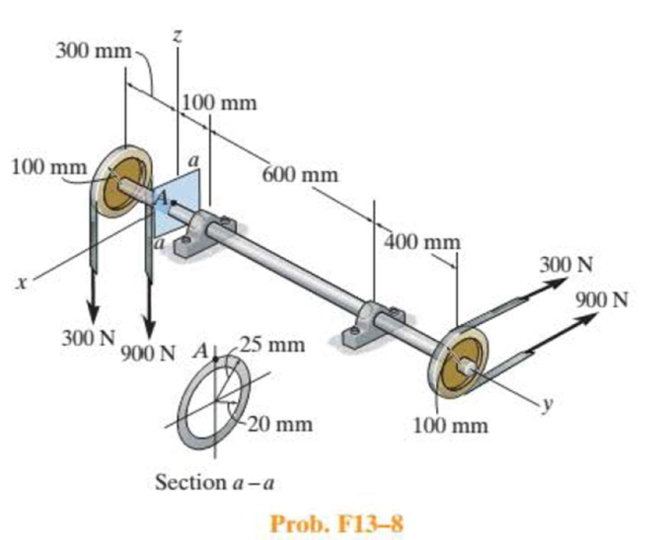
Chapter 13.2, Problem 8FP
Determine the state of stress at point A on the cross section of the shaft at section a–a. Show the results in a differential element at the point.
Expert Solution & Answer
Want to see the full answer?
Check out a sample textbook solution
Students have asked these similar questions
Consider a double-fluid manometer attached to an air pipe shown below. If the specific gravity ofone fluid is 13.8, determine the specific gravity of the other fluid for the indicated absolutepressure of air. Take the atmospheric pressure to be 95 kPa
A race car enters the circular portion of a track that has a radius of 65 m. Disregard the 70 m in the picture. When the car enters the curve at point P, it is traveling with a speed of 120 km/h that is increasing at 5 m/s^2 . Three seconds later, determine the x and y components of velocity and acceleration of the car. I'm having trouble getting the correct y component of acceleration. all the other answers are correct. thank you!
Figure: 06_P041
Copyright 2013 Pearson Education, publishing a Prentice Hall
2. Determine the force that the jaws J of the metal cutters exert on the smooth cable C if 100-N
forces are applied to the handles. The jaws are pinned at E and A, and D and B. There is also
a pin at F.
400 mm
15°
20 mm
A
15°
15
D
B
30 mm² 80 mm
20 mm
400 mm
Figure: 06_P090
Copyright 2013 Pearson Education, publishing as Prentice Hall
15°
100 N
100 N
15°
Chapter 13 Solutions
Statics and Mechanics of Materials Plus Mastering Engineering with Pearson eText - Access Card Package (5th Edition)
Ch. 13.1 - A spherical gas tank has an inner radius of r =...Ch. 13.1 - A pressurized spherical tank is made of...Ch. 13.1 - The thin-walled cylinder can be supported in one...Ch. 13.1 - Prob. 4PCh. 13.1 - Prob. 5PCh. 13.1 - Determine the maximum force P that can be exerted...Ch. 13.1 - Prob. 7PCh. 13.1 - The steel water pipe has an inner diameter of 12...Ch. 13.1 - The steel water pipe has an inner diameter of 12...Ch. 13.1 - The A-36-steel band is 2 in. wide and is secured...
Ch. 13.1 - The gas pipe line is supported every 20 ft by...Ch. 13.1 - Prob. 12PCh. 13.1 - An A-36-steel hoop has an inner diameter of 23.99...Ch. 13.1 - The ring, having the dimensions shown, is placed...Ch. 13.1 - Prob. 15PCh. 13.1 - Prob. 16PCh. 13.1 - Prob. 17PCh. 13.2 - In each case, determine the internal loadings that...Ch. 13.2 - The internal loadings act on the section. Show the...Ch. 13.2 - Determine the normal stress at comers A and B of...Ch. 13.2 - Determine the state of stress at point A on the...Ch. 13.2 - Determine the state of stress at point A on the...Ch. 13.2 - Determine the magnitude of the load P that will...Ch. 13.2 - Prob. 5FPCh. 13.2 - Determine the state of stress at point A on the...Ch. 13.2 - Determine the state of stress at point A on the...Ch. 13.2 - Determine the state of stress at point A on the...Ch. 13.2 - Determine the shortest distance d to the edge of...Ch. 13.2 - Determine the maximum distance d to the edge of...Ch. 13.2 - The plate has a thickness of 20 mm and the force P...Ch. 13.2 - If the load has a weight of 600 lb, determine the...Ch. 13.2 - The steel bracket is used to connect the ends of...Ch. 13.2 - Prob. 23PCh. 13.2 - The column is built up by gluing the two boards...Ch. 13.2 - Prob. 25PCh. 13.2 - The screw of the clamp exerts a compressive force...Ch. 13.2 - Prob. 27PCh. 13.2 - Prob. 28PCh. 13.2 - The joint is subjected to the force system shown....Ch. 13.2 - Prob. 30PCh. 13.2 - The 12-in.-diameter holt hook is subjected to the...Ch. 13.2 - Prob. 32PCh. 13.2 - Prob. 33PCh. 13.2 - Prob. 34PCh. 13.2 - Prob. 35PCh. 13.2 - The drill is jammed in the wall and is subjected...Ch. 13.2 - The drill is jammed in the wall and is subjected...Ch. 13.2 - The frame supports the distributed load shown....Ch. 13.2 - Prob. 39PCh. 13.2 - The rod has a diameter of 40 mm. If it is...Ch. 13.2 - The rod has a diameter of 40 mm. If it is...Ch. 13.2 - The beveled gear is subjected to the loads shown....Ch. 13.2 - The beveled gear is subjected to the loads shown....Ch. 13.2 - Determine the normal-stress developed at points A...Ch. 13.2 - Sketch the normal-stress distribution acting over...Ch. 13.2 - Prob. 46PCh. 13.2 - The solid rod is subjected to the loading shown....Ch. 13.2 - Prob. 48PCh. 13.2 - Prob. 49PCh. 13.2 - The C-frame is used in a riveting machine. If the...Ch. 13.2 - Prob. 51PCh. 13.2 - The uniform sign has a weight of 1500 lb and is...Ch. 13.2 - The uniform sign has a weight of 1500 lb and is...Ch. 13 - The post has a circular cross section of radius c....Ch. 13 - The 20-kg drum is suspended from the hook mounted...Ch. 13 - The 20-kg drum is suspended from the hook mounted...Ch. 13 - Prob. 4RPCh. 13 - If the cross section of the femur at section aa...Ch. 13 - Prob. 6RPCh. 13 - Prob. 7RPCh. 13 - Prob. 8RP
Knowledge Booster


Learn more about
Need a deep-dive on the concept behind this application? Look no further. Learn more about this topic, mechanical-engineering and related others by exploring similar questions and additional content below.Similar questions
- A telemetry system is used to quantify kinematic values of a ski jumper immediately before the jumper leaves the ramp. According to the system r=560 ft , r˙=−105 ft/s , r¨=−10 ft/s2 , θ=25° , θ˙=0.07 rad/s , θ¨=0.06 rad/s2 Determine the velocity of the skier immediately before leaving the jump. The velocity of the skier immediately before leaving the jump along with its direction is ? I have 112.08 ft/s but can't seem to get the direction correct. Determine the acceleration of the skier at this instant. At this instant, the acceleration of the skier along with its direction is ? acceleration is 22.8 ft/s^2 but need help with direction. Need help with velocity direction and acceleration direction please.arrow_forwardFor Problems 18-22 (Table 7-27), design a V-belt drive. Specify the belt size, the sheave sizes, the number of belts, the actual output speed, and the center distance.arrow_forwardonly 21arrow_forward
- only 41arrow_forwardNormal and tangential components-relate to x-y coordinates A race car enters the circular portion of a track that has a radius of 65 m. When the car enters the curve at point P, it is traveling with a speed of 120 km/h that is increasing at 5 m/s^2 . Three seconds later, determine the x and y components of velocity and acceleration of the car. I need help with finding the y component of the total acceleration. I had put -32 but its incorrect. but i keep getting figures around that numberarrow_forwardThe bracket BCD is hinged at C and attached to a control cable at B. Let F₁ = 275 N and F2 = 275 N. F1 B a=0.18 m C A 0.4 m -0.4 m- 0.24 m Determine the reaction at C. The reaction at C N Z F2 Darrow_forward
- Consider the angle bar shown in the given figure A W 240 mm B 80 mm Draw the free-body diagram needed to determine the reactions at A and B when a = 150 mm. This problem could also be approached as a 3-force body using method of Section 4.2B.arrow_forwardA telemetry system is used to quantify kinematic values of a ski jumper immediately before the jumper leaves the ramp. According to the system r=560 ft , r˙=−105 ft/s , r¨=−10 ft/s2 , θ=25° , θ˙=0.07 rad/s , θ¨=0.06 rad/s2 Determine the velocity of the skier immediately before leaving the jump. The velocity of the skier immediately before leaving the jump along with its direction is ? I have 112.08 ft/s but can't seem to get the direction correct. Determine the acceleration of the skier at this instant. At this instant, the acceleration of the skier along with its direction is ? acceleration is 22.8 ft/s^2 but need help with direction. Need help with velocity direction and acceleration direction please.arrow_forwardFor the stop bracket shown, locate the x coordinate of the center of gravity. Consider a = = 16.50 mm. 34 mm 62 mm 51 mm 10 mm 100 mm 88 mm 55 mm 45 mm The x coordinate of the center of gravity is mm.arrow_forward
- In the given figure, the bent rod ABEF is supported by bearings at C and D and by wire AH. The portion AB of the rod is 250 mm long, and the load W is 580 N. Assume that the bearing at D does not exert any axial thrust. H B A с 30° 250 mm D Z 50 mm 300 mm F 250 mm 50 mm W Draw the free-body diagram needed to determine the tension in wire AH and the reactions at C and D.arrow_forwardA 10-ft boom is acted upon by the 810-lb force as shown in the figure. D 6 ft 6 ft E B 7 ft C 6 ft x 4 ft W Draw the free-body diagram needed to determine the tension in each cable and the reaction at the ball-and-socket joint at A.arrow_forwardLocate the center of gravity of the sheet-metal form shown. Given: r = 26.40 mm . 50 mm 40 mm X 150 mm The center of gravity (✗) of the sheet-metal form is The center of gravity (Y) of the sheet-metal form is The center of gravity ( Z ) of the sheet-metal form is mm. mm. (Round the final answer to three decimal places.) mm.arrow_forward
arrow_back_ios
SEE MORE QUESTIONS
arrow_forward_ios
Recommended textbooks for you
 Elements Of ElectromagneticsMechanical EngineeringISBN:9780190698614Author:Sadiku, Matthew N. O.Publisher:Oxford University Press
 Mechanics of Materials (10th Edition)Mechanical EngineeringISBN:9780134319650Author:Russell C. HibbelerPublisher:PEARSON
 Thermodynamics: An Engineering ApproachMechanical EngineeringISBN:9781259822674Author:Yunus A. Cengel Dr., Michael A. BolesPublisher:McGraw-Hill Education
 Control Systems EngineeringMechanical EngineeringISBN:9781118170519Author:Norman S. NisePublisher:WILEY
 Mechanics of Materials (MindTap Course List)Mechanical EngineeringISBN:9781337093347Author:Barry J. Goodno, James M. GerePublisher:Cengage Learning
 Engineering Mechanics: StaticsMechanical EngineeringISBN:9781118807330Author:James L. Meriam, L. G. Kraige, J. N. BoltonPublisher:WILEY
Elements Of Electromagnetics
Mechanical Engineering
ISBN:9780190698614
Author:Sadiku, Matthew N. O.
Publisher:Oxford University Press
Mechanics of Materials (10th Edition)
Mechanical Engineering
ISBN:9780134319650
Author:Russell C. Hibbeler
Publisher:PEARSON
Thermodynamics: An Engineering Approach
Mechanical Engineering
ISBN:9781259822674
Author:Yunus A. Cengel Dr., Michael A. Boles
Publisher:McGraw-Hill Education
Control Systems Engineering
Mechanical Engineering
ISBN:9781118170519
Author:Norman S. Nise
Publisher:WILEY
Mechanics of Materials (MindTap Course List)
Mechanical Engineering
ISBN:9781337093347
Author:Barry J. Goodno, James M. Gere
Publisher:Cengage Learning
Engineering Mechanics: Statics
Mechanical Engineering
ISBN:9781118807330
Author:James L. Meriam, L. G. Kraige, J. N. Bolton
Publisher:WILEY
Everything About COMBINED LOADING in 10 Minutes! Mechanics of Materials; Author: Less Boring Lectures;https://www.youtube.com/watch?v=N-PlI900hSg;License: Standard youtube license