
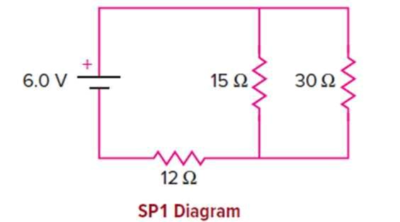
In the circuit shown, the internal resistance of the battery can be considered negligible.
a. What is the equivalent resistance of the two-resistor parallel combination?
b. What is the total current flowing through the battery?
c. What is the voltage drop across the 12-ohm resistor?
d. What is the voltage drop across the 15-ohm resistor?
e. What is the current flowing through the 15 Ω resistor?
f. What is the power dissipated in the 12 Ω resistor?
g. Is the current flowing through the 12 Ω resistor greater or less than that flowing through the 15 Ω resistor? Explain.
(a)
The equivalent resistance of the two parallel resistors.
Answer to Problem 1SP
The equivalent resistance of the two parallel resistors is
Explanation of Solution
Given info: The given circuit is shown below.
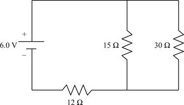
In the given circuit the resistances
Write the formula for the equivalent resistance of two resistances connected in parallel.
Here,
Substitute
Conclusion:
The equivalent resistance of the two parallel resistors is
(b)
The total current flowing in the circuit.
Answer to Problem 1SP
The total current through the circuit is
Explanation of Solution
Given info: The given circuit is shown below.
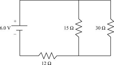
In the given circuit the resistances
Write the formula for the total resistance of the circuit.
Here,
Write the formula for the total current in the circuit.
Here,
Substitute the expression of
From section (a) the equivalent resistance of the two parallel resistances is
Substitute
Conclusion:
The total current through the circuit is
(c)
The voltage drop across
Answer to Problem 1SP
The voltage drop across
Explanation of Solution
Given info: The given circuit is shown below.
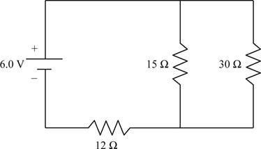
In the given circuit the resistances
The voltage of the battery will get distributed among the
Write the formula for the voltage across the
Here,
From section (a) the equivalent resistance of the parallel connection is
Substitute
Conclusion:
The voltage drop across
(d)
The voltage drop across
Answer to Problem 1SP
The voltage drop across
Explanation of Solution
Given info: The given circuit is shown below.

In the given circuit the resistances
The voltage of the battery will get distributed among the
The voltage drop across
Write the formula for the voltage across the parallel connection of
Here,
From section (c) the voltage across the series resistor is
Substitute
Conclusion:
The voltage drop across
(e)
The current flowing through
Answer to Problem 1SP
The current flowing through
Explanation of Solution
Given info: The given circuit is shown below.
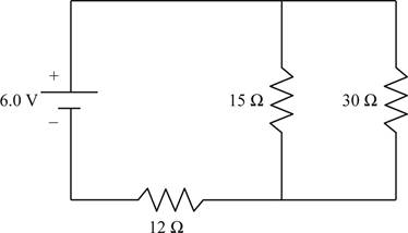
In the given circuit the resistances
Write the formula for current.
Here,
The voltage drop across
Substitute
Conclusion:
The current flowing through
(f)
The power dissipated in
Answer to Problem 1SP
The power dissipated in
Explanation of Solution
Given info: The given circuit is shown below.

In the given circuit the resistances
Write the formula for power.
Here,
From section (c) the voltage drop across
Substitute
Conclusion:
The power dissipated in
(g)
Whether the current through
Answer to Problem 1SP
The current through
Explanation of Solution
Given info: The given circuit is shown below.

In the given circuit the resistances
Since the current is a conserved quantity, in the given circuit, the current through
Conclusion:
The current through
Want to see more full solutions like this?
Chapter 13 Solutions
Physics of Everyday Phenomena
- No chatgpt pls will upvotearrow_forwardthe cable may break and cause severe injury. cable is more likely to break as compared to the [1] ds, inclined at angles of 30° and 50° to the vertical rings by way of a scaled diagram. [4] I 30° T₁ 3cm 3.8T2 cm 200 N 50° at it is headed due North and its airspeed indicat 240 km/h. If there is a wind of 100 km/h from We e relative to the Earth? [3]arrow_forwardCan you explain this using nodal analysis With the nodes I have present And then show me how many KCL equations I need to write, I’m thinking 2 since we have 2 dependent sourcesarrow_forward
- The shear leg derrick is used to haul the 200-kg net of fish onto the dock as shown in. Assume the force in each leg acts along its axis. 5.6 m. 4 m- B Part A Determine the compressive force along leg AB. Express your answer to three significant figures and include the appropriate units. FAB = Value Submit Request Answer Part B Units ? Determine the compressive force along leg CB. Express your answer to three significant figures and include the appropriate units. FCB= Value Submit Request Answer Part C ? Units Determine the tension in the winch cable DB. Express your answer with the appropriate units. 2marrow_forwardPart A (Figure 1) shows a bucket suspended from a cable by means of a small pulley at C. If the bucket and its contents have a mass of 10 kg, determine the location of the pulley for equilibrium. The cable is 6 m long. Express your answer to three significant figures and include the appropriate units. Figure 4 m B НА x = Value Submit Request Answer Provide Feedback < 1 of 1 T 1 m Units ?arrow_forwardThe particle in is in equilibrium and F4 = 165 lb. Part A Determine the magnitude of F1. Express your answer in pounds to three significant figures. ΑΣΦ tvec F₁ = Submit Request Answer Part B Determine the magnitude of F2. Express your answer in pounds to three significant figures. ΑΣΦ It vec F2 = Submit Request Answer Part C Determine the magnitude of F3. Express your answer in pounds to three significant figures. ? ? lb lb F₂ 225 lb 135° 45° 30° -60°-arrow_forward
- The 10-lb weight is supported by the cord AC and roller and by the spring that has a stiffness of k = 10 lb/in. and an unstretched length of 12 in. as shown in. Part A Determine the distance d to maintain equilibrium. Express your answer in inches to three significant figures. 節 ΕΠΙ ΑΣΦ d = *k J vec 5 t 0 ? d C A in. 12 in. Barrow_forwardThe members of a truss are connected to the gusset plate as shown in . The forces are concurrent at point O. Take = 90° and T₁ = 7.5 kN. Part A Determine the magnitude of F for equilibrium. Express your answer to three significant figures and include the appropriate units. F = Value Submit Request Answer Part B 0 ? Units Determine the magnitude of T2 for equilibrium. Express your answer to three significant figures and include the appropriate units. ? T₂ = Value Units T₁ Carrow_forwardpls help on botharrow_forward
 College PhysicsPhysicsISBN:9781938168000Author:Paul Peter Urone, Roger HinrichsPublisher:OpenStax College
 Physics for Scientists and EngineersPhysicsISBN:9781337553278Author:Raymond A. Serway, John W. JewettPublisher:Cengage Learning
 Physics for Scientists and Engineers with Modern ...PhysicsISBN:9781337553292Author:Raymond A. Serway, John W. JewettPublisher:Cengage Learning
 Physics for Scientists and Engineers, Technology ...PhysicsISBN:9781305116399Author:Raymond A. Serway, John W. JewettPublisher:Cengage Learning
 Principles of Physics: A Calculus-Based TextPhysicsISBN:9781133104261Author:Raymond A. Serway, John W. JewettPublisher:Cengage Learning


