
Concept explainers
Videos
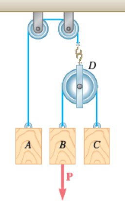
Block A has a mass of 10 kg, and blocks B and C have masses of 5 kg each. Knowing that the blocks are initially at rest and that B moves through 3 m in 2 s, determine (a) the magnitude of the force P, (b) the tension in the cord AD. Neglect the masses of the pulleys and axle friction.
Fig. P12.28
(a)
Find the magnitude of the force P.
Answer to Problem 12.28P
The magnitude of the force P is
Explanation of Solution
Given information:
The mass of block A
The mass of blocks B
The mass of blocks C
The initially block B
The distance of movement for block B
The time taken by block B to move 3 m (t) is 2 s.
Calculation:
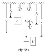
Sketch the system with position of blocks as shown in Figure 1.
Write the general equation of weight (W):
Here, m is the mass, g is the acceleration due to gravity.
Refer Figure (1).
Consider the position of y be positive downward.
Consider the constraint of cord AD.
Write total length of cable connecting block A and block D.
Here,
Differentiate Equation (1) with respect to t to write velocity of the blocks.
Here,
Differentiate Equation (2) with respect to t to write acceleration of the blocks.
Here,
Consider the constraint of cord BC.
Write total length of cable connecting block A and block D.
Here,
Differentiate Equation (4) with respect to t to write velocity of the blocks.
Here,
Differentiate Equation (5) with respect to t to write acceleration of the blocks.
Here,
Substitute
The motion of blocks is uniform.
Find the acceleration of block B
Here,
Substitute
Substitute 3 m for
Sketch the free body diagram of pulley D as shown in Figure 2.
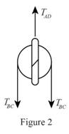
Refer Figure (2),
Consider equilibrium along y-axis.
Here,
Sketch the free body diagram of block A as shown in Figure (3).
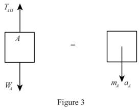
Apply Newton’s law of motion along y-axis.
Here,
Substitute
Sketch the free body diagram of block C as shown in Figure (4).
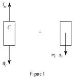
Refer Figure (4),
Apply Newton’s law of motion along y-axis.
Here,
Substitute
Find the tension in the cord BC using Equation (7).
Substitute
Substitute 10 kg for
Sketch the free body diagram of block B as shown in Figure (5).
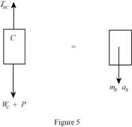
Refer Figure (5),
Find the magnitude of the force P.
Apply Newton’s law of motion along y-axis.
Here,
Substitute
Substitute 5 kg for
Thus, the magnitude of the force P is
(b)
Find the tension in the cord AD.
Answer to Problem 12.28P
The tension in the cord AD is
Explanation of Solution
Calculation:
Find the tension in the cord AD using Equation (8).
Substitute
Thus, the tension in the cord is
Want to see more full solutions like this?
Chapter 12 Solutions
VECTOR MECHANIC
Additional Engineering Textbook Solutions
Thinking Like an Engineer: An Active Learning Approach (4th Edition)
Starting Out with C++ from Control Structures to Objects (9th Edition)
Automotive Technology: Principles, Diagnosis, And Service (6th Edition) (halderman Automotive Series)
Mechanics of Materials (10th Edition)
Modern Database Management
Java How to Program, Early Objects (11th Edition) (Deitel: How to Program)


- A garden hose attached with a nozzle is used to fill a 20-gal bucket. The inner diameter of the hose is 1 in and it reduces to 0.53 in at the nozzle exit. The average velocity in the hose is 8 ft/s and the density of water is 62.4 lbm/ft3. NOTE: This is a multi-part question. Once an answer is submitted, you will be unable to return to this part. Determine the volume and mass flow rates of water through the hose. The volume flow rate of water through the hose is ft3/s. The mass flow rate of water through the hose is lbm/s. The change in time? What is the exit velocity?arrow_forwardA 23-ft3 rigid tank initially contains saturated refrigerant-134a vapor at 160 psia. As a result of heat transfer from the refrigerant, the pressure drops to 50 psia. NOTE: This is a multi-part question. Once an answer is submitted, you will be unable to return to this part. Determine the final temperature. Use data from refrigerant tables. The final temperature is ºF.arrow_forwardA 23-ft3 rigid tank initially contains saturated refrigerant-134a vapor at 160 psia. As a result of heat transfer from the refrigerant, the pressure drops to 50 psia. NOTE: This is a multi-part question. Once an answer is submitted, you will be unable to return to this part. Determine the heat transfer. The heat transfer is Btu.arrow_forward
- The shaft shown in the figure below is subjected to axial loads as illustrated. The diameters of segments AB, BC, and CD are 20mm, 25mm, and 15mm, respectively. If the modulus of elasticity of the material is 610 MPa. Determine the change of A to D lengtharrow_forwardDetermine the final pressure and temperature. The final pressure is kPa. The final temperature is ºC.arrow_forwardAir enters the 1-m2 inlet of an aircraft engine at 100 kPa and 20°C with a velocity of 184 m/s. Determine the volume flow rate, in m3/s, at the engine’s inlet and the mass flow rate, in kg/s, at the engine’s exit. The gas constant of air is R = 0.287 kPa·m3/kg·K. The volume flow rate at the engine’s inlet m3/s. The mass flow rate at the engine’s exit is kg/s.arrow_forward
- The ventilating fan of the bathroom of a building has a volume flow rate of 33 L/s and runs continuously. If the density of air inside is 1.20 kg/m3, determine the mass of air vented out in one day. The mass of air is kg.arrow_forwardA steady-flow compressor is used to compress helium from 15 psia and 70°F at the inlet to 200 psia and 600°F at the outlet. The outlet area and velocity are 0.01 ft2 and 100 ft/s, respectively, and the inlet velocity is 53 ft/s. Determine the mass flow rate and the inlet area. The gas constant of helium is R = 2.6809 psia·ft3/lbm·R. The mass flow rate is lbm/s. The inlet area is ft2.arrow_forward1. The maximum and minimum stresses as well as the shear stress seen subjected the piece in plane A-A. Assume it is a cylinder with a diameter of 12.7mm 2. Draw the Mohr circle for the stress state using software. 3. Selection of the material for the prosthesis, which must be analyzed from the point of safety and cost view.arrow_forward
 Elements Of ElectromagneticsMechanical EngineeringISBN:9780190698614Author:Sadiku, Matthew N. O.Publisher:Oxford University Press
 Mechanics of Materials (10th Edition)Mechanical EngineeringISBN:9780134319650Author:Russell C. HibbelerPublisher:PEARSON
 Thermodynamics: An Engineering ApproachMechanical EngineeringISBN:9781259822674Author:Yunus A. Cengel Dr., Michael A. BolesPublisher:McGraw-Hill Education
 Control Systems EngineeringMechanical EngineeringISBN:9781118170519Author:Norman S. NisePublisher:WILEY
 Mechanics of Materials (MindTap Course List)Mechanical EngineeringISBN:9781337093347Author:Barry J. Goodno, James M. GerePublisher:Cengage Learning
 Engineering Mechanics: StaticsMechanical EngineeringISBN:9781118807330Author:James L. Meriam, L. G. Kraige, J. N. BoltonPublisher:WILEY