
Laboratory Manual for Introductory Circuit Analysis
13th Edition
ISBN: 9780133923780
Author: Robert L. Boylestad, Gabriel Kousourou
Publisher: PEARSON
expand_more
expand_more
format_list_bulleted
Concept explainers
Videos
Textbook Question
Chapter 12, Problem 4P
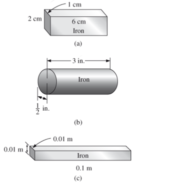
Which section of Fig. 12.35-(a), (b), or (c)-has the largest reluctance to the setting up of flux lines through its longest dimension?
Expert Solution & Answer
Want to see the full answer?
Check out a sample textbook solution
Students have asked these similar questions
Given handwritten correct solution do not use AI
Don't use ai to answer I will report you answer
592
3.44 Use mesh analysis to obtain i, in the circuit of
Fig. 3.90.
ΖΩ
www
ww
ོག་
6 V
+
www
492
192
ww
3 A
+
12 V
Chapter 12 Solutions
Laboratory Manual for Introductory Circuit Analysis
Ch. 12 - Using Appendix E, fill in the blanks in the...Ch. 12 - Repeat Problem 1 for the following table if...Ch. 12 - For the electromagnet in Fig. 12.34 a. Find the...Ch. 12 - Which section of Fig. 12.35-(a), (b), or (c)-has...Ch. 12 - Find the reluctance of a magnetic circuit if a...Ch. 12 - Prob. 6PCh. 12 - Find the magnetizing force H for Problem 5 in SI...Ch. 12 - If a magnetizing force H of 600 At/m is applied to...Ch. 12 - For the series magnetic circuit in Fig. 12.36,...Ch. 12 - Find the current necessary to establish a flux of...
Ch. 12 - a. Find the number of turns N1 required to...Ch. 12 - a. Find the mmf (NI) required to establish a flux...Ch. 12 - For the series magnetic circuit in Fig.12.40 with...Ch. 12 - a. Find the current I required to establish a flux...Ch. 12 - Prob. 15PCh. 12 - Determine the current I1 required to establsh a...Ch. 12 - a. A flux of 0.210-4Wb will establish sufficient...Ch. 12 - For the series-parallel magnetic circuit in Fig....Ch. 12 - Find the magnetic flux established in the series...Ch. 12 - Prob. 20PCh. 12 - Note how closely the B-H curve of cast steel in...
Knowledge Booster


Learn more about
Need a deep-dive on the concept behind this application? Look no further. Learn more about this topic, electrical-engineering and related others by exploring similar questions and additional content below.Similar questions
- Don't use ai to answer I will report you answerarrow_forward2. If the Ce value in Fig. 11-7 is changed to 0.1 μF, is the output still a PWM waveform? Explain. C₁ 0.014 C₂ 100 R₁ 300 HF 8 Vcc 4 reset output 3 discharge 7 2 trigger 5 control voltage U₁ LM555 6 threshold GND ODUCT R₂ 10k ww Bo +12 V 22 R3 1k VR 5k www Re 300 C5 100 ww 8 Vcc 4 reset output 3 2 trigger 7 discharge ли R7 10k PWM Output threshold C6 -0.014 5 control voltage GND Rs 2k CA U2 LM555 1 100μ C3 0.01 Audio lutput Fig. 11-7 Pulse width modulatorarrow_forwardPROD 1. What is the function of VR, in Figs. 11-2 and 11-7. DL RO 0.014 +12V R₁ 1k ww Vin(+) 6 C₁ 0.1μ Audio input HH VRI Vin(-) 4 U1 HА741 10k ww R2 10k UCTS 0.01 μ -12V PWM output Fig. 11-2 The pulse width modulator based on μA741 +12 V ° C₂ 100 R₁ 300 Re 300 Cs 100 ww ww Vcc 4 reset 2 trigger 5 control voltage U₁ LM555 GND www R₂ T₁ 10k output 3 discharge Z Voc output 3 reset VR₁ 5k 2 trigger 7 discharge Ra 1k threshold 6 control 6 threshold voltage GND Rs CA U2 LM555 1 2k 100 Ca 0.01 Audio lutput www R7 10k O PWM C6 -0.014 Fig. 11-7 Pulse width modulator 11/9 Outputarrow_forward
- PRO3. In a point of view of voltage polarity, what is the difference between the output PWM signals in experiments 11-1 and 11-2? H ICTS Experiment 11-1.. Pulse Width Modulator Using uA741 Experiment 11-2 Pulse Width Modulator Using LM555arrow_forward9.58 Using Fig. 9.65, design a problem to help other ed students better understand impedance combinations. Figure 8 65 ww C L R₁ www R2arrow_forwardindicate which of the following switches may be used to control the loads listedarrow_forward
- EXAMPLE 3.15 Consider a sinusoidal signal g(t) = Acos (2лfot+), where the parameters A, fo, and are nonzero constants representing the amplitude, frequency, and initial phase of the sinusoidal signal, respectively. Determine if it is an energy signal or a power signal or neither.arrow_forwardDo part a,b,c and earrow_forward9.69 Find the equivalent admittance Yea of the circuit in Fig. 9.76. 2S 1 S -j3 S -j2 S www ww m m j5 S j1 S www 4 Sarrow_forward
- 9.60 Obtain Zin for the circuit in Fig. 9.67. Zin 25 Ω www Figure 9.67 For Prob. 9.60. j152 m -j500 20 Ω 61 Find in the of Fia 0.68 m 30 Ω j102arrow_forwardFigure 9.58 For Prob. 9.51. 9.52 If V. =8/30° V in the circuit of Fig. 9.59, find I¸. Is 4 10 Ω Figure 9.59 For Prob. 9.52. www -j5Q 5 Ω ww j5Q Voarrow_forward9.64 Find ZT and I in the circuit in Fig. 9.71. 30/90° V 492 www 602 www N ZT (+) Figure 9.71 For Prob. 9.64. -j10 18 Ωarrow_forward
arrow_back_ios
SEE MORE QUESTIONS
arrow_forward_ios
Recommended textbooks for you
 Power System Analysis and Design (MindTap Course ...Electrical EngineeringISBN:9781305632134Author:J. Duncan Glover, Thomas Overbye, Mulukutla S. SarmaPublisher:Cengage Learning
Power System Analysis and Design (MindTap Course ...
Electrical Engineering
ISBN:9781305632134
Author:J. Duncan Glover, Thomas Overbye, Mulukutla S. Sarma
Publisher:Cengage Learning
How does a Transformer work - Working Principle electrical engineering; Author: The Engineering Mindset;https://www.youtube.com/watch?v=UchitHGF4n8;License: Standard Youtube License