In Fig. 12-56, a lead brick rests horizontally on cylinders A and B. The areas of the top faces of the cylinders are related by A A = 2 A B ; the Young’s moduli of the cylinders are related by E A = 2E B . The cylinders had identical lengths before the brick was placed on them. What fraction of the brick’s mass is supported (a) by cylinder A and (b) by cylinder B ? The horizontal distances between the center of mass of the brick and the centerlines of the cylinders are d A for cylinder A and d B for cylinder B. (c) What is the ratio d A /d B ? Figure 12-56 Problem 45.
In Fig. 12-56, a lead brick rests horizontally on cylinders A and B. The areas of the top faces of the cylinders are related by A A = 2 A B ; the Young’s moduli of the cylinders are related by E A = 2E B . The cylinders had identical lengths before the brick was placed on them. What fraction of the brick’s mass is supported (a) by cylinder A and (b) by cylinder B ? The horizontal distances between the center of mass of the brick and the centerlines of the cylinders are d A for cylinder A and d B for cylinder B. (c) What is the ratio d A /d B ? Figure 12-56 Problem 45.
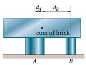
In Fig. 12-56, a lead brick rests horizontally on cylinders A and B. The areas of the top faces of the cylinders are related by AA = 2AB; the Young’s moduli of the cylinders are related by EA = 2EB. The cylinders had identical lengths before the brick was placed on them. What fraction of the brick’s mass is supported (a) by cylinder A and (b) by cylinder B? The horizontal distances between the center of mass of the brick and the centerlines of the cylinders are dA for cylinder A and dB for cylinder B. (c) What is the ratio dA/dB?
A planar double pendulum consists of two point masses \[m_1 = 1.00~\mathrm{kg}, \qquad m_2 = 1.00~\mathrm{kg}\]connected by massless, rigid rods of lengths \[L_1 = 1.00~\mathrm{m}, \qquad L_2 = 1.20~\mathrm{m}.\]The upper rod is hinged to a fixed pivot; gravity acts vertically downward with\[g = 9.81~\mathrm{m\,s^{-2}}.\]Define the generalized coordinates \(\theta_1,\theta_2\) as the angles each rod makes with thedownward vertical (positive anticlockwise, measured in radians unless stated otherwise).At \(t=0\) the system is released from rest with \[\theta_1(0)=120^{\circ}, \qquad\theta_2(0)=-10^{\circ}, \qquad\dot{\theta}_1(0)=\dot{\theta}_2(0)=0 .\]Using the exact nonlinear equations of motion (no small-angle or planar-pendulumapproximations) and assuming the rods never stretch or slip, determine the angle\(\theta_2\) at the instant\[t = 10.0~\mathrm{s}.\]Give the result in degrees, in the interval \((-180^{\circ},180^{\circ}]\).
What are the expected readings of the ammeter and voltmeter for the circuit in the figure below? (R = 5.60 Ω, ΔV = 6.30 V)
ammeter
I =
simple diagram to illustrate the setup for each law- coulombs law and biot savart law
Need a deep-dive on the concept behind this application? Look no further. Learn more about this topic, physics and related others by exploring similar questions and additional content below.


 Physics for Scientists and Engineers: Foundations...PhysicsISBN:9781133939146Author:Katz, Debora M.Publisher:Cengage Learning
 Glencoe Physics: Principles and Problems, Student...PhysicsISBN:9780078807213Author:Paul W. ZitzewitzPublisher:Glencoe/McGraw-Hill
 Principles of Physics: A Calculus-Based TextPhysicsISBN:9781133104261Author:Raymond A. Serway, John W. JewettPublisher:Cengage Learning
 Physics for Scientists and Engineers with Modern ...PhysicsISBN:9781337553292Author:Raymond A. Serway, John W. JewettPublisher:Cengage Learning
 College PhysicsPhysicsISBN:9781285737027Author:Raymond A. Serway, Chris VuillePublisher:Cengage Learning
 University Physics Volume 1PhysicsISBN:9781938168277Author:William Moebs, Samuel J. Ling, Jeff SannyPublisher:OpenStax - Rice University